
Service Manual


119PW / PY Series
Refer to Figure 12.
Disassembly
1. Using any combination of two, 9/16” wrenches
or 9/16” socket and ratchet drive, loosen the
end cap bolts (58) evenly.
2. Keeping the end cap (25) held in place, remove
the four end cap bolts (58).
3. Slowly remove the end cap (25).
4. Remove the valve plate (29).
NOTE: This step is only applicable on PW series
pumps built prior to 0216Pxxxxx.
5. Remove housing alignment pins (26).
6. Remove housing gasket (28).
Inspection
1. Inspect the end cap (25) and/or valve plate (29)
for damage, nicks or unusual wear patterns.
NOTE: Grooving in the valve plate and/or
end cap, made evident when the surface is
checked by dragging a ngernail across the
surface, would be cause for replacement of
the valve plate and/or end cap.
2. Inspect and replace alignment pins (26) if bent
or distorted.
3. Replace the housing O-ring (28) with a new
O-ring before reassembly.
Assembly
1. Install housing O-ring (28) into O-ring seat of
housing (15).
2. Install alignment pins (26) into housing (15).
3. Lubricate the valve plate prior to installation.
Install valve plate (29) with the bronze side
down, contacting the cylinder block.
NOTE: This step is only applicable on PW
series pumps built prior to 0216Pxxxxx.
4. On pumps built without a valve plate, lubricate
the end cap prior to installation.
5 Install end cap (25). Before installing the four
end cap bolts (58), push down on the end cap
(25) verifying alignment and insuring that the
cylinder block pistons spring back and forth.
Install end cap bolts. Tighten, per Table 2, page
110, torque values.
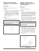
REMOVAL, INSPECTION AND
ASSEMBLY OF THE END CAP AND
VALVE PLATE
Figure 12. PW / PY Pump End Cap
(4X) 58
25
29
28
26
26
15
15
26
26
28
25
(4X) 58
Prior to Serial # 0216Pxxxxx
On or After Serial # 0216Pxxxxx