
Service Manual


4-13Z Master 500 Gas Series Service Manual
4
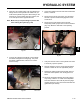
Fig 139 g 58 m-6282
1. Clevis pin in slot 7. Spring
2. Nut against yoke 8. Pivot shaft
3. Adjustment bolt 9. Yoke
4. Pump rod 10. Locknut
5. Double nuts 11. Ball joint
6. Jam nuts
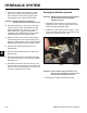
Fig 138 g. 59 m-6278
HYDRAULIC SYSTEM
1. Neutral locked position 3. Neutral position
2. Control lever
6. Pull lever back until the clevis pin (on arm below
pivot shaft) just begins to contact the end of the slot
(just beginning to put pressure on the spring) (Fig.
138).
8. Check where the control lever is relative to notch in
console (Fig. 139). It should be centered allowing
lever to pivot outward to the neutral lock position.
9. If adjustment is needed, loosen the nut and jam nut
against the yoke (Fig. 138).
10. Apply slight rearward pressure on the motion
control lever, turn the head of the adjustment bolt
in the appropriate direction until the control lever is
centered in neutral lock position (Fig. 139).
Note: Keeping rearward pressure on the lever will
keep the pin at the end of the slot and allow
the adjustment bolt to move the lever to the
appropriate position.
11. Tighten the nut and jam nut (Fig. 138).
12. Repeat on the opposite side of the machine.
5. Move the lever to the neutral position but not locked
(Fig. 138).
7. Check where the control lever is relative to notch in
console (Fig. 139). It should be centered allowing
lever to pivot outward to the neutral lock position.