
Service Manual


4-10 Z Master 500 Gas Series Service Manual
4
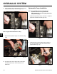
3. Install the two bolts, short spacers, lock washers,
and nuts through the wheel motor, brake linkage and
the frame (Fig. 131).
Fig 131 DSC-3082
HYDRAULIC SYSTEM
Fig 128 DSC-3079
A. Front Spacer (short) B. Back Spacer (long)
Fig 130 DSC-3081
2. Align the brake linkage with the two front bolt holes
(Fig. 130).
Fig 129 DSC-3080
1. Install wheel motor in the frame. Loosely install the
back two bolts, long spacers, lock washers and nuts
(Fig. 129).
A B
Note: There are two different spacers used on the
wheel motors (Fig. 128). The short spacers
are used in the front of the wheel motors(with
the brake linkage) and the long spacers are
used to retain the back of the wheel motor.