
Operator's Manual

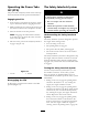


5. Swing the lev er bac k o v er to tighten the baffle
and cam loc ks ( Figure 22 ).
6. If the cams do not loc k the baffle into place or
it is too tight, loosen the lev er and then rotate
the cam loc k. Adjust the cam loc k until the
desired loc king pressure is ac hiev ed.
Figure 22
1. Cam lock
3. Rotate cam to increase or
decrease locking pressure
2. Lever
4. Slot
Positioning the Flow Bafe
T he follo wing figures are only recommendations
for use . Adjustments will v ar y b y g rass type ,
moisture content, and height of g rass .
Note: If the engine po w er dra ws do wn and the
mo w er g round speed is the same , open up the
baffle .
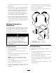
Position A
T his is the full rear position. T he sug g ested use
for this position is a follo ws ( Figure 23 ).
• Use for shor t, light g rass mo wing conditions .
• Use in dr y conditions .
• F or smaller g rass clippings .
• Propels g rass clippings far ther a w a y from the
mo w er .
Figure 23
Position B
Use this position when bag ging .
Figure 24
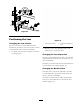
Position C
T his is the full open position. T he sug g ested use
for this position is as follo ws .
• Use in tall, dense g rass mo wing conditions .
• Use in w et conditions .
• Lo w ers the engine po w er consumption.
• Allo ws increased g round speed in hea vy
conditions .
• T his position is similar to the benefits of the
T oro SFS mo w er .
26