
Operator's Manual


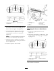
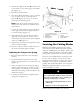


Figure 76
1. Measure here from blade
to hard surface
2. Measure at B and C
7. If the measurements at positions B or C are
not cor rect, loosen the bolt attac hing the rear
c hain to the rear suppor t ar m ( Figure 77 ).
8. Loosen the jam n ut under the rear suppor t
ar m and adjust the adjustment bolt to g et
a measurement of 3-1/8 to 3-1/4 inc hes
( Figure 77 ).
Note: It is recommended that both sides of
the mo w er are adjusted the same distance .
9. Tighten the jam n ut under the rear suppor t
ar m and tighten the bolt securing the c hain to
the rear suppor t ar m.
10. Adjust the opposite side if needed.
Figure 77
1. Rear chain 5. Adjustment bolt
2. Rear support arm
6. Front swivel
3. Bolt
7. Front support arm
4. Jam Nut
Adjusting the Front-to-Rear Mower
Pitch
1. P osition the right blade front-to-rear
( Figure 78 ).
2. Measure the right blade at the A location, from
a lev el surface to the cutting edg e of the blade
tip ( Figure 78 ).
Figure 78
1. Measure here from blade
to hard surface
2. Measure at A and B
3. R ecord this measurement.
58