
Operator's Manual


54
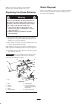
7. If an adjustment is necessary, loosen the jam nut
directly above the trunion roller. Turn the lock nut
below the trunion roller until the correct measurement
is obtained (Fig. 80).
8. Tighten the jam nut directly above the trunion roller
(Fig. 80).
Note: If the 1/4–5/16 inch (5–8 mm) can not be achieved,
remove a pin from either yoke at the ends of the brake
rod. Adjust the length of the rod so 1/4–5/16 inch
(5–8 mm) can be achieved and install the brake rod.
m–7417
1
8
7
5
9
6
3
8
2
4
Figure 80
1. Brake lever—engaged
2. Brake lever—disengaged
3. Spring, 2-3/4 inch (70 mm)
4. Jam nut above trunion
roller
5. Nut below spring bracket
6. Trunion roller
7. 1/4–5/16 inch (5–8 mm)
8. Spring bracket
9. Lock nut below trunion
roller
10. Brake rod
11. Yoke
Servicing the Fuses
The electrical system is protected by fuses. It requires no
maintenance, however, if a fuse blows, check the
component/circuit for a malfunction or short.
Fuse: Main –20 amp, blade-type
Alternator –40 amp, blade-type
1. To gain access to the main fuse, unlatch the seat and
tilt the seat forward. To gain access to the fan and
alternator fuses, raise the seat and tilt the engine cover
forward.
2. To replace a fuse, pull out on the fuse to remove it
(Fig. 81).
m–3653
2
1
Figure 81
1. Fan—40 amp. 2. Main—20 amp.
Servicing the Battery
Battery posts, terminals, and related accessories
contain lead and lead compounds, chemicals
known to the State of California to cause cancer
and reproductive harm. Wash hands after
handling.
Warning
Danger
Battery electrolyte contains sulfuric acid which is
a deadly poison and causes severe burns.
• Do not drink electrolyte and avoid contact with
skin, eyes or clothing. Wear safety glasses to
shield your eyes and rubber gloves to protect
your hands.
Installing the Battery
1. Position battery in the machine.
2. Install the positive (red) battery cable to positive (+)
battery terminal. Secure the cable.
3. Then install negative battery cable and ground wire to
the negative (–) battery terminal. Secure the cable.
4. Slide the red terminal boot onto the positive (red)
battery post.
5. Secure battery with J-bolts, hold down clamp and
2 wing nuts (1/4 inch) (Fig. 82).