
Service Manual


30 PC Series
Refer to Figure 11.
Disassembly
1. Remove charge pump. (See page 27).
2. Remove end cap. (See page 29).
3. Tilt the pump on its side and drain remaining oil.
Lift out the cylinder block assembly (25).
4. Remove the pistons, springs and piston seats.
Inspection
1. Inspect the running surface of the cylinder block
and piston ends for damage, nicks or unusual
wear patterns. The running surface may show
evidence of minor abrasion. This will be normal
wear. If grooved or smeared, replace with a new
cylinder block assembly.
2. Inspect the piston springs for distortion or breaks.
If necessary, replace with a new cylinder block
kit.
3. Inspect the piston seats. Residual oil may cause
these to remain stuck to the inside of the pistons.
Assembly
1. Apply a thin layer of clean oil to the pistons and
springs.
2. Install piston seats into the end of the pistons.
3. Install springs into the pistons.
4. Install each piston, spring and seat assembly into
the cylinder block.
REMOVAL, INSPECTION AND
ASSEMBLY OF THE CYLINDER
BLOCK
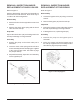
Figure 11. PC Pump Cylinder Block Assembly
NOTE: To assist in cylinder block in-
stallation, a rubber band can be placed
around all of the pistons to hold them
in position.
After the cylinder block is installed, cut
the rubber band and remove it from the
housing.
5. With the pump housing tilted on its side, install
the cylinder block assembly (25) with pistons
contacting the thrust bearing.
NOTE: To check if the cylinder block
assembly is installed correctly, position
the pump housing vertically and sup-
port the housing at the mounting flange.
Push down on the cylinder block. The
cylinder block must move up and down
freely. If it does not, remove the cylin-
der block assembly and reinstall.
6. Install the end cap. (See page 29).
7. Install the charge pump. (See page 27).