
Operator's Manual


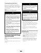
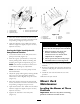


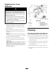

Figure 75
1. Tracking knob 4. Turn this way to track right
2. Hydraulic tank 5. Turn this way to track left
3. Hydraulic pumps
3. Mo v e the motion control lev er forw ard and
rev erse , then bac k to neutral. T he wheel m ust
stop tur ning or slightly cree p in rev erse .
4. Open the throttle to fast. Mak e sure wheel
remains stopped or slightly cree ps in rev erse ,
adjust if necessar y .
Setting the Right-hand Hydraulic
Pump Neutral Position
1. Loosen the loc kn uts at the ball joints on the
pump control rod ( Figure 76 ).
2. Star t the engine , open throttle 1/2 w a y and
release parking brak e . R efer to Star ting and
Stopping the Engine in Operation , pag e 15 .
Note: T he motion control lev er m ust be in
neutral while making any adjustments .
Note: T he front n ut on the pump rod has
left-hand threads .
3. Adjust the pump rod length b y rotating double
n uts on rod, in the appropriate direction,
until wheel is still or slightly cree ps in rev erse
( Figure 76 ).
4. Mo v e the motion control lev er forw ard and
rev erse , then bac k to neutral. T he wheel m ust
stop tur ning or slightly cree p in rev erse .
5. Open the throttle to fast. Mak e sure the wheel
remains stopped or slightly cree ps in rev erse ,
adjust if necessar y .
6. Tighten the loc kn uts at the ball joints
( Figure 76 ).
Figure 76
1. Double nuts 4. Locknut
2. Pump rod 5. Ball joint
3. Adjustment bolt
6. Pumps
Electrical system will not perf or m pr oper
safety shut of f with jumper wir e installed.
• R emo v e jumper wir e fr om wir e
har ness connector and plug
connector into seat s witch when
adjustment is completed.
• Nev er operate this unit with jumper
installed and seat s witch bypassed.
7. After both pump neutrals are set, shut off the
mac hine .
8. R emo v e the jumper wire from the wire har ness
connector and plug the connector into the seat
switc h.
9. Install the seat rod and lo w er the seat into
position.
10. R emo v e the jac k stands .
Mower Deck
Maintenance
Leveling the Mower at Three
Positions
Important: T her e ar e onl y thr ee measuring
positions needed to lev el the mo w er .
54