
Service Manual


S-62
SM-E3B SERIES WSM
DIESEL ENGINE
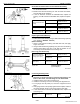
Oil Clearance between Piton Pin and Small End Bushing
1. Measure the piston pin O.D. where it contacts the bushing with
an outside micrometer.
2. Measure the small end bushing I.D. with an inside micrometer,
and calculate the oil clearance.
3. If the oil clearance exceeds the allowable limit, replace the
bushing. If it still exceeds the allowable limit, replace the piston
pin.
W11420110
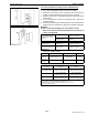
Replacing Small End Bushing
(When removing)
1. Press out the used bushing using a small end bushing replacing
tool. (Refer to “SPECIAL TOOLS”)
(When installing)
1. Clean a new small end bushing and small end hole, and apply
engine oil to them.
2. Using a small end bushing replacing tool, press in a new bushing
(service parts) taking due care to see that the position of the
connecting rod oil hole matches the bushing hole.
[Servicing parts dimension]
W11437590
Connecting Rod Alignment
NOTEQ
• Since the I.D. of the connecting rod small end bushing is the
basis of this check, check bushing for wear beforehand.
1. Install the piston pin into the connecting rod.
2. Install the connecting rod on the connecting rod alignment tool.
3. Put a gauge over the piston pin, and move it against the face
plate.
4. If the gauge does not fit squarely against the face plate, measure
the space between the pin of the gauge and the face plate.
5. If the measurement exceeds the allowable limit, replace the
connecting rod.
W10314620
Oil clearance between
piston pin and small end
bushing
Factory spec.
0.014 to 0.038 mm
0.00056 to 0.0014 in.
Allowable limit
0.10 mm
0.0039 in.
Piston pin O.D. Factory spec.
20.002 to 20.011 mm
0.78748 to 0.78783 in.
Small end bushing I.D. Factory spec.
20.025 to 20.040 mm
0.78839 to 0.78897 in.
Oil clearance between
piston pin and small end
bushing (Spare parts)
Factory spec.
0.015 to 0.075 mm
0.00059 to 0.0029 in.
Allowable limit
0.15 mm
0.0059 in.
Small end bushing I.D.
(Spare parts)
Factory spec.
20.026 to 20.077 mm
0.78843 to 0.79043 in.
(1) Seam
(2) Oil Hole
(A) When Removing
(B) When Installing
(a) 0.79 rad (45°)
Connecting rod
alignment
Allowable limit
0.05 mm
0.002 in.
KiSC issued 03, 2011 A