
Service Manual


ELECTRICAL
6-6 Z580/Z593/Z595 Diesel Service Manual
6
Neutral Safety Switch
Testing How It Works
Testing
Location
Purpose
1. Disconnect the switch from the wiring harness.
2. Verify that continuity exists between the terminals
listed for the switch position. Verify that there is NO
continuity between terminals not listed for the switch
position.
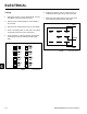
OFF No continuity between terminals
RUN Continuity - B I A X Y
START Continuity - B I S
To gain access to the neutral safety switches, remove
the front storage pocket. There are 2 neutral switches.
One for the right motion control handle and one for the
left motion control handle (Fig. 656).
Fig 656 PICT-4139a
This single pole plunger (normally open) type switch
has two terminals. When the motion control handles are
in the neutral position (handles in the out position), it
pushes on the plunger, closing the contact and connect-
ing the terminals (Fig. 657).
1. Disconnect the switch from the wiring harness.
2. Using a VOM or test light, check fi rst to ensure there
is no continuity between the terminals, plunger out.
3. With the plunger pushed in, there should be contin-
uity between the terminals.
Used to ensure the motion control handles are in neutral
to start the unit. It is actuated by moving the motion
control handles to the neutral position (handles outward).
Fig 657 CLR DSC-2527