
Operator's Manual


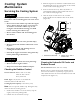

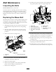


Figure70
1.Oilcoolershield
3.Enginestraps
2.Bolts
5.Removethe4boltsholdingtheoilcoolerand
positiontheoilcoolertotheside(Figure71).
6.Removethe2boltsholdingthefanandfanplateto
themachine(Figure71).
Figure71
1.Oilcooler
3.Fanplate
2.Fan4.Alternatorbelt
7.Loosenthebottomboltandremovetheupperbolt
holdingthealternatorandcover(Figure72).
8.Rotatethealternatorcovertothesideandremove
thebeltfromthepulleysandalternator.
9.Installanewbeltaroundthepulleysandthe
alternator(Figure72).
10.Installthefanandfanplatetothemachinewiththe
2boltspreviouslyremoved(Figure71).
11.Installtheoilcoolerwiththe4boltspreviously
removed(
Figure71).
12.Installtheoilcoolershieldandenginestrapsto
therearframewiththe4boltspreviouslyremoved
(Figure70).
13.Installtheenginestrapstothesideofthemachine
(
Figure70).
14.Tightenthebottomboltandinstalltheupperbolt
holdingthealternatorandcover(Figure72).
TensioningtheAlternatorBelt
1.Placeahandlebetweenthealternatorandcylinder
block.
2.Adjustthealternatortotheoutsideuntilthereis
1/4to11/32inch(7to9mm)deectioninthebelt
betweentheengineandthealternatorpulleyswith
22.1lbsofforce(10kgf)(
Figure72).
3.Tightenthealternatorbolts.
4.Checkthedeectioninthebeltagainandadjustthe
beltifneeded.
5.Ifthedeectioniscorrect,tightenthebottomand
upperbolt(
Figure72).
Figure72
1.Alternator4.Topbolt
2.Alternatorbelt5.Bottombolt
3.Deection,1/4to
11/32inch(7to9mm)with
22.1lbsofforce(10kgf)
50