
Operator's Manual


ProductOverview
g019888
Figure4
1.Height-of-cutdecklift
pedal
6.Rollbar
2.Transportlock
7.Seatbelt
3.Parkingbrakelever8.Fuelcap
4.Controls
9.Mowerdeck
5.Motioncontrollever
10.Casterwheel
Controls
Becomefamiliarwithallofthecontrolsbeforeyoustartthe
engineandoperatethemachine(Figure4andFigure5).
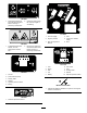
Figure5
1.Hourmeter
6.Glowpluglight
2.Ignitionswitch7.Enginetemperaturelight
3.Fuelselectorvalve8.Throttlecontrol
4.Audiblealarm
9.PTOswitch
5.Glowplugswitch
HourMeter
Thehourmeterrecordsthenumberofhourstheenginehas
operated.Itoperateswhentheengineisrunning.Usethese
timesforschedulingregularmaintenance(Figure5).
SafetyInterlockIndicators
Therearesymbolsonthehourmeterandtheyindicatewitha
blacktrianglethattheinterlockcomponentisinthecorrect
position(Figure6).
BatteryIndicatorLight
WhentheignitionkeyisinitiallyturnedtotheRunposition
forafewseconds,thebatteryvoltagewillbedisplayedinthe
areawherethehoursarenormallydisplayed.
Thebatterylightturnsonwhentheignitionisturnedon
andwhenthechargeisbelowthecorrectoperatinglevel
(
Figure6).
Figure6
1.Safetyinterlocksymbols
3.Batterylight
2.Hourmeter
ThrottleControl
ThethrottlecontrolisvariablebetweenFastandSlow.
BladeControlSwitch(PTO)
Thebladecontrolswitch(PTO)isusedtoengagetheelectric
clutchtodrivethemowerbladeswiththemotioncontrol
leversinthecenter,un-lockedposition.Pulltheswitchupto
engagethebladesandrelease.Todisengagetheblades,push
thebladecontrolswitch(PTO)down.
NeutralLockPosition
Theneutrallockpositionisusedwiththesafetyinterlock
systemandtodetermineneutralposition.
IgnitionSwitch
Thisswitchisusedtostartthemowerengineandhasthree
positions:Start,Run,andOff.
15