
Service Manual


ENGINE
5-21Z580/Z593/Z595 Diesel Service Manual
5
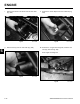
7. Position the stub shaft to the fl ywheel (Fig. 481).
Fig 481 PICT-3642
8. Install the 5 mounting bolts securing the stub shaft to
the fl ywheel. Torque the mounting bolts to 145 + 20
in-lbs. (196 + 27 Nm) (Fig. 482).
Fig 482 PICT-3647
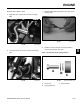
9. Install the 3 sets of engine isolation mounts and the
3 isolation mount spacers (Fig. 483).
Fig 483 PICT-3652
Note: The frame bracket is sandwiched between
the engine isolation mounts with the spacer
running through the middle (Fig. 484).
Fig 484 PICT-3628a