
Manual


Children or bystanders may be injured if
they move or attempt to operate the tractor
while it is unattended.
Always remove the ignition key and set the
parking brake when leaving the machine
unattended, even if just for a few minutes.
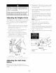
Adjusting the Height-of-Cut
The height-of-cut is adjusted from 1-1/2 to 5 inch
(38 to 127 mm) in 1/4 inch (6 mm) increments
by relocating the clexds pin into different hole
locations.
,
,
,
Raise the height-of-cut lever to the transport
position (also the 5 inch (127 ram) cutting
height position) (Figure 17).
To adjust, remove the clevis pin from the
height-of-cut bracket (Figure 17).
Select a hole in the height-of-cut bracket
corresponding to the height-of-cut desired
and, insert the clevis pin (Figure 17).
4. Move the lever to the selected height•
2
,
,
,
,
,
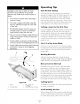
Disengage the PTO, move the motion control
levers to the neutral locked position and set
the paring brake.
Stop the engine, remove the ke), and wait for
all moving parts to stop before leaving the
operating position.
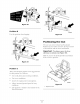
After adjusting the height-of-cut, adjust the
rollers by removing the fange nut, bushing,
spacer, and bolt (Figure 18 , Figure 19 and
Figure 20 ).
Note: The two middle rollers will not have a
spacer (Figure 19).
Select a hole so the anti-scalp roller is
positioned to the nearest corresponding
height-of-cut desired•
Install the flange nut bushing, spacer, and bolt.
Torque to 40-45 ft-lb (54-61 N.m) (Figure 18,
Figure 19 and Figure 20 ).
Repeat this adjustment on the other anti-scalp
rollers.
1.
2.
3.
Figure 18
Anti-scalp roller 4. Flange Nut
Spacer 5. Bolt
Bushing
5
G000942
Figure 1 7
1. Height of cut lever 2. Clevis Pin
G000940
Adjusting the Anti-Scalp
Rollers
Whenever you change the height-of-cut, it is
recommended to adjust the height of the anti-scalp
rollers.
23