
Service Manual


6-15Z Master 500 Gas Series Service Manual
6
ELECTRICAL
Verify that 12 volts DC is present across the two
terminals when the ignition key is in the RUN position. If
so, and the meter is not running, replace the meter. If 12
volts is not present, check the connections. The meter is
a permanently sealed unit and is not repairable.
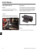
Fig 350 DSC-2560
Since a normal clock might be affected by variations in
voltage and current, the hour meter is made up of an
electric “winder” and a mechanical clock movement.
When power is applied, a coil is energized to wind the
movement. The movement unwinds in about 2 seconds.
As it nishes its rotation, it re-energizes the coil so that
the cycle can start over (Fig. 350).
How It Works
Testing
VOLTMETER GAUGE
This gauge indicates the voltage across the battery.
The voltmeter is located to the left side of the operator,
on the control panel (Fig. 351).
Fig 351 DSC-2563
Purpose
Location
The meter movement is proportional to the voltage
level across the two terminals of the battery. This is
accomplished by placing a resistor in parallel with the
meter.
How It Works