
Operator's Manual


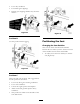


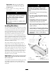


Figure 19
1. Anti-scalp roller 4. Flange Nut
2. Spacer
5. Bolt
3. Bushing
Figure 20
1. Anti-scalp roller 3. Flange Nut
2. Bushing 4. Bolt
Figure 21
1. Anti-scalp roller 4. Flange Nut
2. Spacer
5. Bolt
3. Bushing
Adjusting the Flow Bafe
T he mo w er disc harg e flo w can be adjusted for
different types of mo wing conditions . P osition the
cam loc ks and baffle to gi v e the best quality of cut.
1. Diseng ag e the PTO , mo v e the motion control
lev ers to the neutral loc k ed position and set
the parking brak e .
2. Stop the engine , remo v e the k ey , and w ait for
all mo ving par ts to stop before lea ving the
operating position.
3. T o adjust the cam loc ks , swing the lev er up to
loosen the cam loc k ( Figure 22 ).
4. Adjust the baffle and cam loc ks in the slots to
the desired disc harg e flo w .
5. Swing the lev er bac k o v er to tighten the baffle
and cam loc ks ( Figure 22 ).
6. If the cams do not loc k the baffle into place or
it is too tight, loosen the lev er and then rotate
the cam loc k. Adjust the cam loc k until the
desired loc king pressure is ac hiev ed.
Figure 22
1. Cam lock
3. Rotate cam to increase or
decrease locking pressure
2. Lever
4. Slot
Positioning the Flow Bafe
T he follo wing figures are only recommendations
for use . Adjustments will v ar y b y g rass type ,
moisture content, and height of g rass .
Note: If the engine po w er dra ws do wn and the
mo w er g round speed is the same , open up the
baffle .
Position A
T his is the full rear position. T he sug g ested use
for this position is a follo ws .
• Use for shor t, light g rass mo wing conditions .
24