
Service Manual


CHASSIS
3-56 Z580/Z589 DFI Z Master Service Manual
3
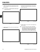
6. Install the neutral return yoke onto the neutral return
bolt (Fig. 202).
Fig 202 PICT-3126a
8. Tighten the jam nut to secure the neutral adjustment
yoke (Fig. 204).
Note: The neutral return spring may need adjust
ment after the motion contol levers are instal
led. The motion control lever, when moved to
reverse position, should spring back to the
neutral postions when the handles are let go.
Fig 204 PICT-3142a
7. Position the left hand neutral return yoke to the left
hand motion control tab and install a clevis pin and
cotter pin (Fig. 203).
Fig 203 PICT-3124a
5. Install a bolt, washer and nut securing the left hand
control rod ball joint to the hydrostatic pump control
arm (Fig. 201).
Note: The washer is installed between the ball joint
and the control arm.
Fig 201 PICT-3131a