
Operator's Manual


a measurement of 3-1/8 to 3-1/4 inc hes
( Figure 68 ).
Note: It is recommended that both sides of
the mo w er are adjusted the same distance .
9. Tighten the jam n ut under the rear suppor t
ar m and tighten the bolt securing the c hain to
the rear suppor t ar m.
10. Adjust the opposite side if needed.
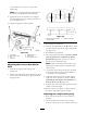
Figure 68
1. Rear chain 5. Adjustment bolt
2. Rear support arm
6. Front swivel
3. Bolt
7. Front support arm
4. Jam Nut
Adjusting the Front-to-Rear Mower
Pitch
1. P osition the right blade front-to-rear
( Figure 69 ).
2. Measure the right blade at the A location, from
a lev el surface to the cutting edg e of the blade
tip ( Figure 69 ).
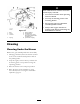
Figure 69
1. Measure here from blade
to hard surface
2. Measure at A and B
3. R ecord this measurement.
4. Measure the right blade at the B location, from
a lev el surface to the cutting edg e of the blade
tip ( Figure 69 ).
5. R ecord this measurement.
6. T he mo w er blade should be a 1/4 to 3/8 inch
(6 to 10 mm) lo w er at position A than at
position B ( Figure 69 ). If it is not cor rect,
proceed to the follo wing ste ps .
Note: Both of the front swi v els need to be
adjusted the same amount to maintain equal
c hain tension.
7. Loosen the front swi v el jam n uts , at the front
of the right and left swi v els , appro ximately a
1/2 inc h (13 mm) ( Figure 68 ).
8. Adjust the lift n uts on both the left and the
right side of the mac hine to ac hiev e 1/4 to
3/8 inch (6 to 10 mm) lo w er in fr ont at A
than in the r ear at B ( Figure 68 ).
9. Tighten both swi v el jam n uts ag ainst the front
swi v el to loc k the height.
10. Chec k to mak e sure there is equal tension on
the c hains and adjust ag ain if needed.
Adjusting the Compression Spring
1. Raise the mo w er lift lev er to the transpor t
position.
2. Chec k the distance betw een the tw o larg e
w ashers , it needs to be 10-1/2 inc hes (26.7 cm)
52