
Service Manual


4-18 Z Master 500 Gas Series Service Manual
4
HYDRAULIC SYSTEM
Hydraulic Flow Testing Procedure
2. Start the engine and run at low idle speed. Slowly
engage the motion control lever. If the wheel does
not rotate immediately, it may be necessary to spin
the wheel by hand to start purging air that is trapped
in the system (Fig. 151).
Fig 151 DSC-3124
3. When the wheel begins to spin on its own, keep it
engaged until the wheel drives smoothly (minimum 2
minutes).
4. Check the hydraulic uid level and add uid as
required to maintain proper level.
5. Repeat this procedure on the opposite wheel.
Fig 152 DSC-3125
Note: Cleanliness is a key factor in successful ow
testing of the hydraulic system. Thoroughly
clean all exposed surfaces prior to any type
of maintenance. Cleaning all parts by using
a solvent wash and air drying is usually
adequate. As with any precision equipment,
all parts must be kept free of foreign material
and chemicals. Protect all exposed sealing
areas and open cavities from damage and
foreign material.
Flow tester P/N 70661, contact your DSM to
order.
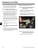
1. Lift the back of the unit so the rear tires (left and
right) is off the ground. Place jack stands under the
rear frame to support the unit. Remove the rear tire;
in this case the left rear tire is being removed (Fig.
152).
Note: Be careful not to place jack stands near
any moving parts or areas not capable of
supporting the weight of the machine.
Fig 150 DSC-3123
The traction system is self bleeding, however, it may be
necessary to bleed the system if uid is changed or after
work is performed on the system.
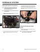
1. Raise the machine so the wheels are off the ground
and supported with jack stands (Fig. 150).
Purging the Hydraulic System