
Service Manual


4-4 Z Master 500 Gas Series Service Manual
4
HYDRAULIC SYSTEM
Hydrostatic Pump Installation
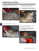
10. Loosen and remove the two bolts and nuts retaining
the hydrostatic pump to the frame (Fig. 107).
Fig 107 DSC-3000
11. Remove the hydrostatic pump from the frame (Fig.
108).
Fig 108 DSC-3002
Fig 110 DSC-2999
2. Install the pump suction hydraulic line, located on
top of the hydrostatic pump, that comes from the
hydraulic lter (Fig. 110).
Fig 109 DSC-3000
Note: As a reminder, prior to connecting the
hydraulic lines, the O-rings should be
replaced with new ones and lightly lubricated
with petroleum jelly.
1. Install the hydrostatic pump to the frame. Install and
tighten the two bolts and nuts (Fig. 109).
Note: Engine shield removed for clarity.
12. For service work on the pump refer to the Hydro-
Gear BDP10A/16A/21L Service Manual, form
#492-4789.