
Service Manual


6-3Z Master 500 Gas Series Service Manual
6
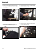
Liquid-Cooled Engine Model: Three relays located on
the right rear radiator support arms, next to the ROPS
(Fig. 323).
Fig 323 DSC-3162
Fig 325 relay pin diagram
87 87a
86
85
30
1. Coil: Terminals 85 and 86 are connected to an
internal coil. Applying 12 volts to either terminal
energizes the coil turning it into an electromagnet.
2. Switch: Terminals 30, 87, and 87a are actually
part of a single pole, double throw (SPDT) switch.
Terminal 30 is the common lead. The switch is spring
loaded so that terminals 30 and 87a are connected
when the relay is not energized. When the relay is
energized, the magnetic eld overcomes the spring
loaded switch and connects terminals 30 and 87
(Fig 325).
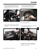
A relay is an electrically actuated switch (Fig. 324).
Fig 324 DSC-2517
A. Fan Relay (toward front) C. Kill Relay (back)
B. Start Relay (middle)
How It Works
ELECTRICAL
A
B
C