
Operator's Manual


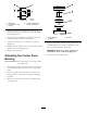


Figure47
1.Centerbolt3.Leftsupportplate
2.Alignmenthole
4.Springloadedidler
5.Ifadjustmentisrequired,loosentheidlerplateto
adjustit(Figure48).
6.Insertaratchetorbreakerbarintothesquareholein
theidlerplatetoadjustthetension(Figure48).
7.Toincreasebelttension,rotatetheratchetorbreaker
bartomovethexedidleruntilyoufeelincreased
resistanceandthespring-loadedidlerpulleystops
moving(Figure48).
Note:Donotincreasethebelttensionbeyondthe
pointwherethexedidlerarmstops.
8.Whileholdingthebelttension,tightentheidlerplate
boltsthatsecuretheidlerplate(Figure48).
Figure48
1.Rachetwithshort
extensionorbreaker
bar
2.IdlerplatewithSquare
hole
9.Checkthedistancefromtherubberstopandthe
armofthespringloadedidlerpulleywhentheidler
plateistightened.Itneedstobe0to1/4inch(0to
6mm)fromtherubberstop(Figure49).
Figure49
1.Springloadedidlerpulley
4.Idlerpulleyarm
2.Topalignmenthole5.Belt
3.0to1/4inchgap(0to6
mm)
6.Rubberbumper
10.Adjustthebelttensionandtheidlerplate,if
necessary,andtightenallhardwaresecurely
(Figure48).
11.Iftheidlerplatecontactstheendoftheadjustment
slotandmorebelttensionisrequired,asmallchange
totherightsidexedidlercancreatemorebelt
tensionadjustment(Figure50).
Figure50
1.Fixedidler2.Adjustmentslot
CheckingandReplacingthe
PumpDriveBelt
ServiceInterval:Every50hours—Checkthepump
drivebelt.
1.Checkthepumpdrivebeltforwear.
2.Pullthespringloadedidlerdownandremove
tractionbeltfromtheengineandhydropump
pulleys(Figure51).Removebeltbetweenpulleys.
38