
Operator's Manual

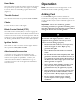


Figure17
1.Heightofcutlever2.ClevisPin
2.Toadjust,removetheclevispinfromthe
height-of-cutbracket(Figure17).
3.Selectaholeintheheight-of-cutbracket
correspondingtotheheight-of-cutdesiredand,
inserttheclevispin(Figure17).
4.Movethelevertotheselectedheight.
AdjustingtheAnti-Scalp
Rollers
Wheneveryouchangetheheight-of-cut,itis
recommendedtoadjusttheheightoftheanti-scalp
rollers.
AdjustingtheOuterRoller
1.DisengagethePTO,movethemotioncontrol
leverstotheneutrallockedposition,andsetthe
parkingbrake.
2.Stoptheengine,removethekey,andwaitforall
movingpartstostopbeforeleavingtheoperating
position.
3.Afteradjustingtheheight-of-cut,removetheange
nut,bushing,spacer,andbolt(Figure18).
Figure18
1.Outerroller
4.Bolt
2.Spacer
5.Nut
3.Bushing
4.Selectaholesothattheouterrollerispositioned
tothenearestcorrespondingheight-of-cutdesired
(Figure18).
5.Installtheouterroller,bushing,spacer,bolt,and
nut(Figure18).
6.Torquetheboltto40to45ft-lb(54to61N⋅m).
AdjustingtheCenterRollers
1.DisengagethePTO,movethemotioncontrol
leverstotheneutrallockedposition,andsetthe
parkingbrake.
2.Stoptheengine,removethekey,andwaitforall
movingpartstostopbeforeleavingtheoperating
position.
3.Afteradjustingtheheight-of-cut,removetheange
nut,bushing,andbolt(Figure19).
20