
Operator's Manual


22
1. Raise the height-of-cut lever to the transport position
(also the 5 inch [127 mm] cutting height position)
(Fig. 20).
2. To adjust, remove the hairpin cotter and clevis pin from
the height-of-cut bracket (Fig. 20).
3. Select the hole in the height-of-cut bracket
corresponding to the height-of-cut desired, and insert
the clevis pin (Fig. 20).
4. Secure the clevis pin with the hairpin cotter (Fig. 20).
5. Move the lever to the selected height.
1
3
2
M–4164
Figure 20
1. Height of cut lever
2. Clevis pin
3. Hairpin cotter
Adjusting the Anti-Scalp
Rollers
Whenever you change the height-of-cut it is recommended
to adjust the height of the anti-scalp rollers.
1. Disengage the power take off (PTO) and turn the
ignition key to Off. Move the control levers to the
neutral locked position and apply the parking brake.
Remove the key.
2. After adjusting the height-of-cut, remove the flange nut
and spring disk while holding the stud with a wrench
(Fig. 21).
Note: Do not remove the wheel nut and washer (Fig. 21).
3. Select a hole so that the gage wheel is positioned to the
nearest corresponding height-of-cut desired (Fig. 21).
4. Reinstall the flange nut and spring disk (Fig. 21).
5. Repeat the adjustment on the other gage wheels.
m–4167
1
2
3
4
5
Figure 21
1. Gage wheel
2. Stud
3. Spring disk
4. Flange nut
5. Wheel nut and washer.
Do not remove.
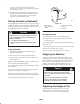
Positioning the Seat
Changing the Seat Position
The seat can move forward and backward. Position the seat
where you have the best control of the machine and are
most comfortable.
1. To adjust, move the lever sideways to unlock seat
(Fig. 22).
2. Slide the seat to the desired position and release lever to
lock in position.
Changing the Seat Suspension
The seat can be adjusted to provide a smooth and
comfortable ride. Position the seat where you are most
comfortable.
1. To adjust, turn the knob in front either direction to
provide the best comfort (Fig. 22).