
Operator's Manual


22
1. Raise the height-of-cut lever to the transport position
(also the 5 inch (127 mm) cutting height position)
(Fig. 20).
2. To adjust, remove hairpin cotter and clevis pin from
height-of-cut bracket (Fig. 20).
3. Select hole in height-of-cut bracket corresponding to
the height-of-cut desired and, insert clevis pin
(Fig. 20).
4. Secure clevis pin with hairpin cotter (Fig. 20).
5. Move lever to selected height.
1
3
2
M–4164
Figure 20
1. Height of cut lever
2. Clevis Pin
3. Hairpin Cotter
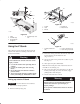
Using the Lift Assist Lever
The lift assist lever is used along with the height–of–cut
lever for raising the deck. This allows for easier raising of
the deck.
1. Place your foot onto lift assist lever.
2. Press on lift assist while pulling up on height–of–cut
lever (Fig. 21).
1
m–5028
Figure 21
1. Lift Assist Lever
Adjusting the Anti-Scalp
Rollers
Whenever you change the height-of-cut it is
recommended to adjust the height of the anti-scalp rollers.
1. Disengage the power take off (PTO) and turn the
ignition key to off. Move levers to neutral locked
position and apply parking brake. Remove the key.
2. After adjusting height-of-cut remove flange nut and
spring disk while holding stud with wrench (Fig. 22).
Note: Do not remove the wheel nut and washer (Fig. 22).
3. Select hole so gage wheel is positioned to the nearest
corresponding height-of-cut desired (Fig. 22).
4. Reinstall the flange nut and spring disk. Torque to
40–45 ft.–lb. (54–61 Nm) (Fig. 22).
5. Repeat adjustment on other gage wheels.