
Operator's Manual


23
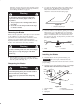
3. Select hole so gage wheel is positioned to the nearest
corresponding height-of-cut desired (Fig. 21).
4. Reinstall the flange nut and spring disk. Torque to
40–45 ft–lb (54.2–61.0 Nm) (Fig. 21).
5. Repeat adjustment on other gage wheels.
m–4161
1
2
3
4
5
Figure 21
1. Gage Wheel
2. Stud
3. Spring Disk
4. Flange Nut
5. Wheel nut and washer. Do
Not Remove.
Positioning the Seat
The seat can move forward and backward. Position the
seat where you have the best control of the machine and
are most comfortable.
1. To adjust, move the lever sideways to unlock seat
(Fig. 22).
2. Slide the seat to the desired position and release lever
to lock in position.
1
m–3655
Figure 22
1. Adjustment lever
Pushing the Machine by Hand
Important Always push the machine by hand. Never
tow the machine because hydraulic damage may occur.
To Push the Machine
1. Disengage the power take off (PTO) and turn the
ignition key to off. Move levers to neutral locked
position and apply parking brake.
2. Rotate the by-pass valves counterclockwise 1 turn to
push. This allows hydraulic fluid to by-pass the pump
enabling the wheels to turn (Fig. 23).
Important Do not rotate by-pass valves more than
1 turn. This prevents valves from coming out of the body
and causing fluid to run out.
3. Disengage parking brake before pushing.
To Operate the Machine
1. Rotate the by-pass valves clockwise 1 turn to operate
machine (Fig. 23).
Note: Do not over tighten the by–pass valves.
Note: The machine will not drive unless by-pass valves
are turned in.
m–6124
1
Figure 23
1. By-pass valve
Using a Rollover Protection
System
Rollover protection systems (ROPS) are available for
many riding machines. Contact an Authorized Service
Dealer for information on obtaining ROPS for your
machine.