
Operator's Manual


18
7
1
2
5
4
10
M–4507
36
8
9
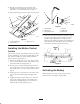
Figure 9
1. Ignition switch
2. Motion control lever
3. Parking brake lever
4. Throttle
5. Choke
6. Power take off (PTO)
7. Height-of-Cut lever
8. Fuel cap
9. Fuel shut off lever
10. Hour meter
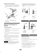
Using the Hour Meter
The hour meter records the number of hours the engine
has operated. It operates when the engine is running. Use
these times for scheduling regular maintenance.
1
m–3077
Figure 10
1. Hour meter
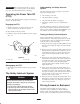
Switching Fuel Tanks
The unit has two fuel tanks, located on the left and right
sides. Each tank connects to the fuel shut off valve in the
control panel. From there a common fuel line leads to the
engine (Fig. 11).
To use the right side fuel tank rotate the fuel shut off valve
1/4 turn to the right from the off location. This uses fuel
from the right side tank only. When the right hand fuel
tank is empty, move the fuel shut off valve 1/4 turn to the
left from the off position.
Close fuel shut off valve, on front panel before
transporting or storing machine.
1
Figure 11
1. Shut off valve
Operating the Parking Brake
Always set the parking brake when you stop the machine
or leave it unattended.
Setting the Parking Brake
1. Move the motion control levers (Fig. 9) out to the
neutral lock position.
2. Pull back and up on the parking brake lever to set the
parking brake (Fig. 12). The parking brake lever
should stay firmly in the engaged position.
Parking brake may not hold machine parked on a
slope and could cause personal injury or property
damage.
Do not park on slopes unless wheels are chocked
or blocked
Warning