FORM NO. 3322–434 Rev A Z–Master 250 Series Z255 with 62” SFS Side Discharge Mower Model No. 74203–992000 & Up Operator’s Manual IMPORTANT: Read this manual carefully. It contains information about your safety and the safety of others. Also become familiar with the controls and their proper use before you operate the product.
Introduction Thank you for purchasing a Toro product. All of us at Toro want you to be completely satisfied with your new product, so feel free to contact your local Authorized Service Dealer for help with service, genuine replacement parts, or other information you may require. Whenever you contact your Authorized Service Dealer or the factory, always know the model and serial numbers of your product.
Contents Safety . . . . . . . . . . . . . . . . . . . . . . . . . . . . . . . . . Safe Operating Practices . . . . . . . . . . . . . . Slope Chart . . . . . . . . . . . . . . . . . . . . . . . . . Safety and Instruction Decals . . . . . . . . . . Gasoline and Oil . . . . . . . . . . . . . . . . . . . . . . . . Recommended Gasoline . . . . . . . . . . . . . . Stabilizer/Conditioner . . . . . . . . . . . . . . . . Filling the Fuel Tank . . . . . . . . . . . . . . . . . Check Engine Oil Level . . . . . . . . .
Safety This machine meets or exceeds CPSC blade safety requirements for rotary mowers and the B71.4 1990 specifications of the American National Standards Institute, in effect at time of production. Improper use or maintenance by the operator or owner can result in injury. To reduce the potential for injury, comply with these safety instructions and always pay attention to the safety alert symbol, which means CAUTION, WARNING, or DANGER—“personal safety instruction.
Safety General Operation 1. 2. Read, understand, and follow all instructions in the operator’s manual and on the machine before starting. Allow only responsible adults who are familiar with the instructions to operate the machine. 3. Clear the area of objects such as rocks, toys, wire, etc., which could be picked up and thrown by the blade. 4. Be sure the area is clear of other people before mowing. Stop the machine if anyone enters the area. 5. Never carry passengers. 6.
Safety Slope Operation Slopes are a major factor related to loss-of-control and tip-over accidents, which can result in severe injury or death. All slopes require extra caution. If you cannot back up the slope or if you feel uneasy on it, do not mow it. • Check carefully for overhead clearances (i.e. branches, doorways, electrical wires) before driving under any objects and do not contact them. DO NOT • Do not operate machine on hillsides or slopes exceeding 15°.
Safety Children Tragic accidents can occur if the operator is not alert to the presence of children. Children are often attracted to the machine and the mowing activity. Never assume that children will remain where you last saw them. The following requirements must be followed to prevent injury to children. 1. Keep children out of the mowing area and under the watchful care of another responsible adult. 2. Be alert and turn the machine off if children enter the area. 3.
Safety Slope Chart Read all safety instructions on pages 3–5.
Safety 7
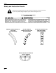
Safety Safety and Instruction Decals Safety decals and instructions are easily visible to the operator and are located near any area of potential danger. Replace any decal that is damaged or lost. TOP OF CONSOLE UNDER SEAT (Part No. E513747) ON RIGHT SIDE OF HEIGHT OF CUT PLATE (Part No E633345) ON LEFT SIDE OF HEIGHT–OF–CUT PLATE (Part No E633706) BELOW CENTER OF CONSOLE (Part No. E633346) 8 ON TOP OF CONSOLE LEFT AND RIGHT SIDES (Part No.
Safety UNDER FOOTREST (Part No. E633766) ON RUBBER FLAP BEHIND SEAT (Part No. E513748) ON RUBBER FLAP BEHIND SEAT (Part No. E303517) ON TOP OF RIGHT ENGINE BAFFLE (Part No. E633771) ON CONSOLE AND RUBBER FLAP BEHIND SEAT (Part No. E633462) ON CONTROL PANEL (Part No.
Safety ON LEFT SIDE GAS TANK (Part No. 99–4632) ON HYDRAULIC TANK (Part No. 65–2690) ON TOP OV HYDRAULIC RESERVOIR (Part No. E513890) ON HYDRAULIC RESERVOIR MOUNTING BRACKET (Part No. E513929) ON DECK SUPPORT FRAME (Part No.
Safety # %'( & ! %'( & %'( & # %'( & UNDER FOOTREST AND (2) UNDER PULLEY COVERS (Part No.
Gasoline and Oil Recommended Gasoline Use UNLEADED Regular Gasoline suitable for automotive use (85 pump octane minimum). Leaded regular gasoline may be used if unleaded regular is not available. POTENTIAL HAZARD • In certain conditions gasoline is extremely flammable and highly explosive. WHAT CAN HAPPEN IMPORTANT: Never use methanol, gasoline containing methanol, or gasohol containing more than 10% ethanol because the fuel system could be damaged. Do not mix oil with gasoline.
Gasoline and Oil Stabilizer/Conditioner Filling the Fuel Tank Add the correct amount of gas stabilizer/conditioner to the gas. Using a stabilizer/conditioner in the machine: 1. Shut the engine off and set the parking brake. 2. Clean around each fuel tank cap and remove the cap. Add unleaded regular gasoline to both fuel tanks, until the level is 1/4 to 1/2 inch (6 mm to 13 mm) below the bottom of the filler neck. This space in the tank allows gasoline to expand.
Assembly Loose Parts Note: Use the chart below to verify all parts have been shipped. DESCRIPTION QTY.
Assembly Install Drive Wheels Install Seat Retaining Rod 1. Uncrate mower. 4. 1. Remove wheel bolts or nuts from rear wheel hubs. Tilt seat up. Remove 5/16” (8mm) locknut from bolt attaching seat retaining rod to seat frame (Fig. 2). 5. 2. Align holes. Mount drive wheels with the valve stem to the outside of the traction unit. 3. Secure using wheel bolts or nuts provided. Torque to 95ft–lbs (128 NSM).
Assembly Install Motion Control Levers 8. Remove the (4) 3/8–16 x 1” (26 mm) bolts and (4) 3/8” spring washers which attach the motion control levers to the control arm shafts for shipping (Fig. 3). 9. Place the levers (with the mounting plate towards the rear) on the outside of the control arm shaft and secure with (4) 3/8–16 x 1” (26 mm) bolts and (4) 3/8” spring washers (Fig. 3). 12.
Assembly Activate the Battery 2. Bulk electrolyte with 1.260 specific gravity must be purchased from a local battery supply outlet. Remove filler caps from the battery. Slowly pour electrolyte into each cell until the electrolyte level is up to the lower part of the tube (Fig. 5). 1 1. Remove the battery from the machine. IMPORTANT: Be careful not to damage the long vent tube when removing the battery box.
Assembly Install Battery 6. Position battery in tray with terminal posts toward the engine (Fig. 7). WHAT CAN HAPPEN • Battery gasses can explode. 7. Slide the red terminal boot onto the positive (red) battery cable. HOW TO AVOID THE HAZARD 8. Install the positive (red) battery cable to positive (+) battery terminal then negative battery cable and ground wire to the negative (–) battery terminal. 9. Secure cables with (2) 1/4 x 3/4” (19 mm) bolts 1/4” washers and 1/4” locknuts (Fig. 7).
Assembly Hydraulic System Check the Leveling of Mower Deck Checking the Hydraulic Fluid Check the hydraulic fluid level before engine is first started. Check the level of the deck before the machine is first put into use. Fluid Type: Mobil 1 15W–50 synthetic motor oil. Refer to Mower Leveling and Compression Spring Adjustment sections in the Maintenance section on page 50. IMPORTANT: Use only oil specified. Other fluids could cause system damage. Hydraulic System Oil Capacity: 2.1 qt. (2.0 l) 1.
Operation Think Safety First Parking Brake Please carefully read all the safety instructions on pages 2–8. Knowing this information could help you, your family, pets or bystanders avoid injury. Always set the parking brake when you stop the machine or leave it unattended. Setting the Parking Brake Controls 1. Move the motion control levers (Fig. 1) out to the neutral lock position. Become familiar with all the controls (Fig. 1) before you start the engine and operate the machine. 2.
Operation Releasing the Parking Brake 1. 6. Push forward and down on the parking brake lever release the parking brake (Fig. 2). The parking brake is “DISENGAGED” and the lever rests against the brake stop. IMPORTANT: Do not engage starter for more than 10 seconds at a time. If engine fails to start allow 30 second cool-down period between attempts. Failure to follow these instructions can burn out starter motor. 1 7. 2 Turn ignition key “START” to energize starter. When engines starts, release key.
Operation Stopping 1. Move the throttle lever to “SLOW” (Fig. 5). 2. Turn the ignition key to “OFF” (Fig. 6). Note: 3. 4. If the engine has been working hard or is hot, let it idle for a minute before turning the ignition key “OFF.” This helps cool the engine before it is stopped. In an emergency, the engine may be stopped by turning the ignition key to “OFF.” Pull wire off spark plug(s) to prevent possibility of accidental starting before transporting or storing machine.
Operation The Safety Interlock System Understanding the Safety Interlock System The safety interlock system is designed to prevent the engine from starting unless: • You are sitting on the seat • The parking brake is “ENGAGED” • The power take off (PTO) is disengaged “OFF” • The motion control levers are in neutral locked position The safety interlock system also is designed to stop the engine when the traction controls are moved from the locked position with the parking brake “ENGAGED” or if you r
Operation Driving Forward or Backward The throttle control regulates the engine speed as measured in rpm (revolutions per minute). Place the throttle control in the “FAST” position for best performance. Always operate in the full throttle position when mowing. Forward 1. Release the parking brake; refer to Setting the Parking Brake, page 20. 2. Move levers to the center, un-locked position. 3. To go forward, slowly push the motion control levers forward (Fig. 8).
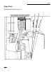
Operation Instruments Fuel Tanks Hour Meter The hour meter records the number of hours the engine has operated. It operates when the engine is running. Use these times for scheduling regular maintenance. 1 The unit has two fuel tanks, located on the left and right sides. Each tank connects to the fuel shut off valve in the control panel. From there a common fuel line leads to the engine (Fig. 10). To use the right side fuel tank rotate the fuel shut off valve 1/4 turn to the right from the off location.
Operation Adjusting Height-of-Cut Adjusting Anti-Scalp Rollers The height-of-cut is adjusted from 1-1/2” to 5” (38 to 127 mm) in 1/4” (6 mm) increments by relocating clevis pin in different hole locations. Whenever you change the height-of-cut it is recommended to adjust the height of the anti-scalp rollers. 1. Raise the height-of-cut lever to the transport position (also the 5” (127 mm) cutting height position) (Fig. 11). Note: 2.
Operation Stud Method Center Rollers 1. 1. Disengage the power take off (PTO) and turn the ignition key to “OFF”. Move controllers to neutral locked position and apply parking brake. 1. After adjusting height-of-cut, remove bolt and flange nut (Fig. 14). 2. Select hole so gage wheel is positioned to the nearest corresponding height-of-cut desired (Fig. 14). 2. Disengage the power take off (PTO) and turn the ignition key to “OFF” to stop the engine.
Operation Positioning the Seat Pushing the Machine by Hand The seat can move forward and backward. Position the seat where you have the best control of the machine and are most comfortable. 1. To adjust, move the lever sideways to unlock seat (Fig. 15). 2. Slide the seat to the desired position and release lever to lock in position. IMPORTANT: Always push the machine by hand. Never tow the machine because hydraulic damage may occur. To Push the Machine 1.
Operation Tips for Mowing Grass Cutting Speed Fast Throttle Setting To improve cut quality, use a slower ground speed in certain conditions. For best mowing and maximum air circulation, operate the engine at “FAST.” Air is required to thoroughly cut grass clippings, so do not set the height-of-cut so low as to totally surround the mower by uncut grass. Always try to have one side of the mower free from uncut grass, which allows air to be drawn into the mower.
Maintenance Service Interval Chart Service Operation Each Use 8 Hours 25 Hours Hydraulic fluid–check level Initial Initial X Oil—check level 50 Hours 100 Hours X Initial X Oil Filter–change (200 hours or every other oil change)* Hydraulic filter–change Storage Service X X Oil—change* Safety System—check 200 Hours Initial X X X X X X X Chassis—grease* X X Linkage bushings—oil* X X Foam Air Cleaner—service* X X Paper Air Cleaner—replace* X Spark Plug(s)—check X X Belts—c
Maintenance POTENTIAL HAZARD • If you leave the key in the ignition switch, someone could start the engine. WHAT CAN HAPPEN • Accidental starting of the engine could seriously injure you or other bystanders. HOW TO AVOID THE HAZARD • Remove the key from the ignition switch and pull the wire(s) off the spark plug(s) before you do any maintenance. Also push the wire(s) aside so it does not accidentally contact the spark plug(s).
Maintenance Inspecting the Blades Checking for Bent Blades 1. Inspect the cutting edges (Fig 17). If the edges are not sharp or have nicks, remove and sharpen the blades. Refer to Sharpening the Blades on page 34. 1. 2. Inspect the blades, especially the curved area (Fig. 17). If you notice any damage, wear, or a slot forming in this area (item 3 in Fig. 17), immediately install a new blade. Rotate the blades until the ends face forward and backward (Fig. 18).
Maintenance 1 POTENTIAL HAZARD • A blade that is bent or damaged could break apart and pieces could be thrown at bystanders or at you as you use the mower. WHAT CAN HAPPEN • Pieces of blade that may be thrown could seriously injure or kill you or bystanders. HOW TO AVOID THE HAZARD 2 3 4 M-4165 Figure 20 1. Sail Area of Blade 2. Blade 3. Spring Disk 4. Blade Bolt • Always replace bent or damaged blade with a new blade. • Never file or create sharp notches in the edges or surfaces of blade.
Maintenance Sharpening the Blades Installing the Blades 1. IMPORTANT: The curved part of the blade must be pointing upward toward the inside of the mower to ensure proper cutting. POTENTIAL HAZARD • When sharpening blade, pieces of blade could be accidentally thrown. 2. WHAT CAN HAPPEN • Thrown objects can cause serious eye injury. HOW TO AVOID THE HAZARD • Wear proper eye protection when sharpening blade. 1. Use a file to sharpen the cutting edge at both ends of the blade (Fig. 21).
Maintenance Air Cleaner 3. Carefully slide the foam element off the paper element (Fig. 23). Foam Element: Clean and re-oil after every 25 operating hours. 4. Unscrew the cover nut and remove the cover and paper element (Fig. 23). Paper Element: Replace after every 100 operating hours. Note: Service the air cleaner more frequently (every few hours) if operating conditions are extremely dusty or sandy. Removing the Foam and Paper Elements 1. 2. Cleaning the Foam and Paper Elements 1.
Maintenance 2. Paper Element Engine Oil A. Lightly tap the element on a flat surface to remove dust and dirt (Fig. 25). Change oil: B. Inspect the element for tears, an oily film, and damage to the rubber seal. IMPORTANT: Never clean the paper element with pressurized air or liquids, such as solvent, gas, or kerosene. Replace the paper element if it is damaged, or cannot be cleaned thoroughly. • After the first 8 operating hours. • After every 100 operating hours.
Maintenance Checking Oil Level Changing/Draining Oil 1. 1. Start the engine and let it run five minutes. This warms the oil so it drains better. 2. Park the machine so that the drain side is slightly lower than the opposite side to assure the oil drains completely. Disengage the power take off (PTO), set the parking brake, and turn the ignition key to “OFF” to stop the engine. Remove the key. 3. Place a pan below the oil drain. Remove the oil drain cap (Fig. 27). 4.
Maintenance Spark Plug Change Oil Filter Replace the oil filter every 200 hours or every other oil change. Note: 1. Change oil filter more frequently when operating conditions are extremely dusty or sandy. Drain the oil from the engine; refer to Changing/Draining Oil, page 37. 2. Remove the old filter and wipe the filter adapter (Fig. 28) gasket surface. 3. Pour new oil of the proper type in through the center hole. Stop pouring when the oil reaches the bottom of the threads.
Maintenance Greasing and Lubrication Checking the Spark Plug 1. Look at the center of the spark plug(s) (Fig. 30). If you see light brown or gray on the insulator, the engine is operating properly. A black coating on the insulator usually means the air cleaner is dirty. IMPORTANT: Never clean the spark plug(s). Always replace the spark plug(s) when it has: a black coating, worn electrodes, an oily film, or cracks. 2. Lubricate the machine when shown on the CHECK SERVICE REFERENCE AID decal (Fig. 31).
Maintenance Where to Add Grease Lubricate the grease fittings as shown on the CHECK SERVICE REFERENCE AID decal (Fig. 31). Cleaning the Cooling Systems Before each use, check and clean cooling screen. Remove any build–up of grass, dirt or other debris from the oil cooler screen and engine air intake. Every 100 hours clean oil cooler, engine cylinder and cylinder head cooling fins. Also clean around carburetor, governor levers and linkage.
Maintenance Fuel Filter Fuel Tank Replace the fuel filter after every 200 operating hours or yearly, whichever occurs first. Draining The Fuel Tank Replacing the Fuel Filter POTENTIAL HAZARD • In certain conditions gasoline is extremely flammable and highly explosive. Never install a dirty filter if it is removed from the fuel line. 1. Disengage the power take off (PTO) and turn the ignition key to “OFF” to stop the engine. Move controllers to neutral locked position and apply parking brake.
Maintenance 4. Pull the fuel line off fuel filter (Fig. 35). Open fuel shut-off valve and allow gasoline to drain into a gas can or drain pan. Note: 5. Now is the best time to install a new fuel filter because the fuel tank is empty. Install the fuel line onto the fuel filter. Slide the hose clamp close to the fuel filter to secure the fuel line (Fig. 35). Hydraulic System Checking the Hydraulic Fluid Check the hydraulic fluid level before engine is first started. and after every 25 operating hours.
Maintenance 3. Place drain pan under filter, remove the old filter and wipe the filter adapter gasket surface clean (Fig. 37). POTENTIAL HAZARD • Hydraulic fluid escaping under pressure can penetrate skin and cause injury. WHAT CAN HAPPEN • Fluid accidentally injected into the skin must be surgically removed within a few hours by a doctor familiar with this form of injury or gangrene may result.
Maintenance 10. Check fluid level in hydraulic tank and add to raise level to cover bottom of screen. DO NOT OVER FILL. 1 3 Check Hydraulic Lines After every 100 operating hours, check hydraulic lines and hoses for leaks, loose fittings, kinked lines, loose mounting supports, wear, weather and chemical deterioration. Make necessary repairs before operating. Note: Keep areas around hydraulic system clean from grass and debris build up. 2 m–1256 Figure 38 1. Hydraulic filter 2. Gasket 3.
Maintenance Adjusting Motion Controls 4 1 1 Adjusting Handle Neutral If motion control levers do not align, or move easily into the console notch, adjustment is required. Adjust each lever, spring and rod separately. Note: 1. 2. 6 Motion control levers must be installed correctly. See Install Motion Control Levers on page 16. Stop engine, remove ignition key and tilt seat forward. Begin with either the left or right motion control lever.
Maintenance 10. Slide seat forward, disconnect prop rod and tilt seat fully forward. 16. Repeat on opposite side of unit. Tighten locknuts against ball joints. 11. Disconnect electrical connector from the seat safety switch. Temporarily install a jumper wire across terminals in the wiring harness connector. 12. Loosen locknut at ball joint on pump control rod (Fig. 39). Note: The front nut of each rod has left–hand threads.
Maintenance Replacing the Pump Drive Belt Adjustment Parking Brake Check pump drive belt for wear after every 50 hours of operation. Check parking brake for proper adjustment. 1. 2. 3. 1. Disengage brake lever (lever down). Pull spring loaded idler down and remove traction belt from the engine and hydro pump pulleys (Fig. 40). Remove belt between pulleys. 2. Measure the length of the spring. Measurement should be 2.75” (70 mm) between washers (Fig. 41).
Maintenance Fuse Service Interval/Specification The electrical system is protected by fuses. It requires no maintenance, however, if a fuse blows check component/circuit for malfunction or short. Fuse: Main F1–20 amp, blade-type Alternator F2–20 amp, blade-type 1. Raise the seat to gain access to fuse holder (Fig. 42). 2. To replace fuses pull out on the fuse to remove it (Fig. 42). 2 1 m–3653 Figure 42 1. Main-30 amp 48 2.
Maintenance Battery Check the electrolyte level in the battery every 25 hours. Always keep the battery clean and fully charged. Use a paper towel to clean the battery case. If the battery terminals are corroded, clean them with a solution of four parts water and one part baking soda. Apply a light coating of grease to the battery terminals to prevent corrosion. IMPORTANT: Do not overfill the battery because electrolyte (sulfuric acid) can cause severe corrosion and damage to the chassis. 4.
Maintenance Mower Leveling 1. 2. Position mower on a flat surface. Stop the engine, set the parking brake, remove the key and disconnect the spark plug wire(s) from the spark plug(s). Lift up on four (4) top chain attachment bolts, in the slots, to take slack out of chains and tighten flange lock nuts. (Deck is still supported by two rear and one front blocks under mower) 9.
Maintenance Greasing the Bearings Replacing the Deck Belt The cutting unit must be lubricated regularly. Refer to the Service Interval Chart on page 30. Grease with No. 2 general purpose lithium base or molybdenum base grease. Squealing when the belt is rotating, blades slipping when cutting grass, frayed belt edges, burn marks and cracks are signs of a worn deck belt. Replace the deck belt if any of these conditions are evident. 1.
Maintenance Replacing the PTO Drive Belt Squealing when the belt is rotating, blades slipping when cutting grass, frayed belt edges, burn marks and cracks are signs of a worn drive belt. Replace the PTO drive belt if any of these conditions are evident. 1. 2 Stop the engine, set the parking brake, remove the key and disconnect the spark plug wire(s) from the spark plug(s). m–3744 1 2. Remove the clutch retaining strap and unplug clutch terminal from wire harness (Fig. 48). 3.
Maintenance 8. If the fixed idler contacts the end of the adjustment slot and more belt tension is required, a small change in the lengthen the push arms can be made (Fig. 51). 9. To lengthen, loosen jam nut and rotate ball joint counterclockwise, one turn at a time. Adjust each side the same amount. 3 1 1 2 m–3740 Figure 51 1. Push arm 2. 15” (381 mm) nominal 3. Jam nut 4. Ball joint 10.
Maintenance Replacing the Grass Deflector 4 7 2 8 9 4 5 POTENTIAL HAZARD • An uncovered discharge opening will allow objects to be thrown in operator’s or bystander’s direction. Also, contact with blade could occur. 1 WHAT CAN HAPPEN • Thrown objects or blade contact can cause serious injury or kill you or bystanders. 3 5 HOW TO AVOID THE HAZARD 6 • Never operate mower unless grass deflector or catcher are installed. 1.
Maintenance Wiring Diagram 55
Maintenance Cleaning and Storage 1. 2. Disengage the power take off (PTO), set the parking brake and turn the ignition key to “OFF” to stop the engine. Remove spark plug wire. Remove the key. Remove grass clippings, dirt, and grime from the external parts of the entire machine, especially the engine and hydraulic system. Clean dirt and chaff from the outside of the engine’s cylinder head fins and blower housing. IMPORTANT: You can wash the machine with mild detergent and water.
Troubleshooting PROBLEM Starter does not crank Engine g will not start,, starts hard,, or f il to fails t keep k running. i Engine g loses power. p POSSIBLE CAUSES CORRECTIVE ACTION 1. Blade control (PTO) is ENGAGED. 1. Move blade control (PTO) to DISENGAGED. 2. Parking brake is not on. 2. Set parking brake. 3. Operator is not seated. 3. Sit on the seat. 4. Battery is dead. 4. Charge the battery. 5. Electrical connections are corroded or loose. 5.
Troubleshooting PROBLEM Engine g overheats. Machine does not drive. Abnormal vibration. Uneven cutting g height. g 58 POSSIBLE CAUSES CORRECTIVE ACTION 1. Engine load is excessive. 1. Reduce ground speed. 2. Oil level in crankcase is low. 2. Add oil to crankcase. 3. Cooling fins and air passages under engine blower housing are plugged. 3. Remove obstruction from cooling fins and air passages. 1. Traction belt is worn, loose or broken. 1. Contact Authorized Service Dealer. 2.
Troubleshooting PROBLEM Blades do not rotate. POSSIBLE CAUSES CORRECTIVE ACTION 1. Drive belt is worn, loose or broken. 1. Install new drive belt. 2. Drive belt is off pulley. 2. Install drive belt and check adjusting shafts and belt guides for correct position. 3. Deck belt is worn, loose or broken. 3. Install new deck belt. 4. Deck belt is off pulley. 4. Install deck pulley and check the idler pulley, idler arm and spring for correct position and function.
A OneĆYear Limited Warranty (A TwoĆYear Full Warranty for Residential Use) LCE What Is Covered By This Express Warranty? The Toro Company promises to repair any TORO Product used for commercial, institutional, or rental purposes if defective in materials or workmanship. The following time frames apply from the date of purchase: Product Warranty Period All Products . . . . . . . . . . . . . . . . . . 1 year All Spindles . . . . . . . . . . . . . . . . . . .