
Operator's Manual


Installation
10
Install Wire Harness
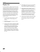
8. Unplug clutch connector from existing main
wire harness (Fig. 14). Located below and
behind muffler.
9. Insert new jumper connectors of new wire
harness between clutch connector and main wire
harness. Align connectors and push together
firmly so latches lock (Fig. 14).
3 m-3566
2
1
4
3
Figure 14
1. Clutch connector
2. Main wire connector
3. New jumper connector
4. Latch
10. Route remainder of new wire harness around
back of engine to the left vertical frame member,
following main wire harness. Attach wire ties to
keep harness out of castor wheel (Fig. 15).
1
m-3567
3
2
Figure 15
1. New wire harness
2. Existing wire harness
3. Castor wheel
11. Route new wire harness along left horizontal
frame member and secure to existing wire
harness with wire ties to keep harness away from
engine.
12. Loosen left console clamp and two lower front
mounting bolts. Pull console away from left
frame member to gain access to holes in frame
and console. Route new wire harness through
holes in frame and into bottom of console
(Fig. 16).
13. Remove instrument panel and remove plug in
opening or drill a 1-1/8” (29 mm) hole for
buzzer 1-1/2” (39 mm) below hour meter.
14. Insert buzzer, from the rear, and secure with
retaining ring (Fig. 16).
15. Connect new wire harness pink lead to +
terminal and green lead to – terminal (Fig. 16).
16. Coil excess wire harness behind panel
1
m-3568
8
3
6
5
4
2
7
9
Figure 16
1. Console clamp
2. Front bolt
3. Hole in console
4. 1-1/8” (29 mm) Hole 1-1/2”
(39 mm) below hourmeter
5. Buzzer
6. Retaining ring
7. Pink +
8. Green –
9. Wire harness