
Operator's Manual


39
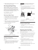
Checking the Wheel Hub
Slotted Nut
Check after every 500 operating hours.
The slotted nut needs to be torqued to 125 ft–lb (170 N⋅m).
1. Disengage the PTO, move the motion control levers to
the neutral locked position and set the parking brake.
2. Stop the engine, remove the key, and wait for all
moving parts to stop before leaving the operating
position.
3. Remove the cotter pin.
4. Torque the slotted nut to 125 ft–lb (170 N⋅m) (Fig. 49).
5. Check the distance from the bottom of the slot in the
nut to the inside edge of the hole. Two threads or less
should be showing (Fig. 49).
6. If more than two threads are showing, remove the nut
and install a washer between the hub and nut (Fig. 49).
7. Torque the slotted nut to 125 ft–lb (170 N⋅m) (Fig. 49).
8. Tighten the nut until the next set of slots line up with
the hole in the shaft (Fig. 49).
9. Install the cotter pin.
3
m–4638
1
2
4
5
Figure 49
1. Slotted nut
2. Two threads or less
showing
3. Hole in threaded shaft
4. Washer (if needed)
5. Slot
Leveling the Mower at Three
Positions
Important There are only three measuring positions
needed to level the mower.
Setting Up the Machine
1. Position mower on a flat surface.
2. Disengage the PTO, move the motion control levers to
the neutral locked position and set the parking brake.
3. Stop the engine, remove the key, and wait for all
moving parts to stop before leaving the operating
position.
4. Check tire pressure of all four tires. If needed, adjust to
13 psi (90 kPa)
5. Position the mower to the 3 inch (76 mm) height–of–cut
position.
6. Inspect the four chains. The chains need to have
tension.
Note: The rear chains need to be adjusted to the top of the
slot, where attached to the mower.
• If one rear chain is loose, lower (loosen) the front
support arm on the same side. Refer to Adjusting the
Front–to–Rear Mower Pitch on page 40.
• If one front chain is loose, raise (tighten) the front
support arm for that chain. Refer to Adjusting the
Front–to–Rear Mower Pitch on page 40.
Leveling the Mower Side–to–Side
1. Position the right blade front-to-rear (Fig. 50).
2. Measure the right blade at the B location (Fig. 50), from
a level surface to the cutting edge of the blade tip
(Fig. 51).
3. Record this measurement. This measurement needs to
be 3–1/8 to 3–1/4 inches.
4. Position the left blade front-to-rear (Fig. 50).
5. Measure the left blade at the C location (Fig. 50), from
a level surface to the cutting edge of the blade tip
(Fig. 51).
6. Record this measurement. This measurement needs to
be 3–1/8 to 3–1/4 inches.