
Operator's Manual


21
1. Raise the height-of-cut lever to the transport position
(also the 4-1/2 inch (114 mm) cutting height position)
(Fig. 18).
2. To adjust, remove hairpin cotter and clevis pin from
height-of-cut bracket (Fig. 18).
3. Select hole in height-of-cut bracket corresponding to
the height-of-cut desired, and insert clevis pin
(Fig. 18).
4. Secure clevis pin with hairpin cotter (Fig. 18).
1
m–4122
3
2
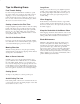
Figure 18
1. Height-of-cut lever
2. Clevis pin
3. Hairpin cotter
5. Lower height–of–cut lever onto clevis pin.
Adjusting Anti-Scalp Rollers
Whenever you change the height-of-cut it is
recommended to adjust the height of the anti-scalp rollers.
Adjusting the Outside Rollers
1. Disengage the PTO, move the motion control levers to
the neutral locked position and set the parking brake.
2. Stop the engine, remove the key, and wait for all
moving parts to stop before leaving the operating
position.
3. After adjusting height-of-cut remove nut and washer
while holding stud with wrench (Fig. 19).
Note: Do not remove the wheel nut and washer (Fig. 19).
4. Select hole so gage wheel is positioned to the nearest
corresponding height-of-cut desired (Fig. 19).
5. Reinstall the flange nut and spring disk. Torque to
40–45 ft-lb (54.2–61.0 N m) (Fig. 19).
6. Repeat adjustment on other gage wheels.
m–4167
1
2
3
4
5
1
Figure 19
1. Gage wheel
2. Stud
3. Washer
4. Nut
5. Wheel nut and washer.
Do not remove.
Adjusting the Center Rollers
1. Disengage the PTO, move the motion control levers to
the neutral locked position and set the parking brake.
2. Stop the engine, remove the key, and wait for all
moving parts to stop before leaving the operating
position.
3. After adjusting height-of-cut, remove bolt and nut
(Fig. 20).
4. Select hole so gage wheel is positioned to the nearest
corresponding height-of-cut desired (Fig. 20).
Note: Do not adjust rollers to support the deck.
5. Reinstall the bolt, center rollers and nut (Fig. 20).
m–4124
1
2
3
Figure 20
1. Center rollers and spacer
2. Nut
3. Bolt