
Service Manual


Motor Rotor/Ball
(SA)
Pump Rotor/Ball
(SA)
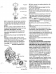
Pump and Motor Rotor Inspection
51
Disassemble and Inspect the rotor assem-
bly
in the following manner. Remove the
piston balls from the rotor, one at a time,
working clockwise from the letter stamped in
the rotor face. Place the piston balls in a
prepared container (use a container such as
an egg carton or ice cube tray to hold the
balls).
Note:
The balls must be replaced in the same
bores from which they were removed because
they are all select fit.
Check for broken or collapsed springs in the
motor rotor. When broken or collapsed springs
are found with no other irregularities, the
springs may be replaced individually without
replacing the complete motor rotor assembly.
Inspect the piston balls. They must be smooth
Inspect the rotor bores, rotor bushing and
pintle journals for irregularities or excessive
clearance. The ball piston to rotor bore clear-
ance is select fit electronically from
.0002
inch
[,005
mm] to
.0006
inch
[,015
mm]. When
irregularities are noted, replace the complete
rotor assembly. Install the ball pistons in their
matching bores. Hold them in place with a
rubber band or separate race.
and completely free of any irregularities.
Socket Head Cap Screw
(4)
Charge Pump Plate
Transaxle with Charge Pump
52
To inspect the charge pump assembly,
use a
5/32
hex key to remove the cap
screws from the charge pump plate.
53
Remove the charge pump plate from
the housing.
54
Remove the charge pump gerotor
from the housing.
55
The pump and motor journals and cam ring
dowel cannot be removed once they have
been installed in the housing.
Note:
Inspect the pump and motor journals for
any irregularities.
If
any are found, the housing
must be replaced.
56
In most cases, we do not recommend
removal of the dampening pistons for inspec-
tion or cleaning. Normal flushing should be all
that is required for cleaning.
Dump
Valve
Fitting
Nut
and
O-ring
Transaxle with Dump Valve
57
To remove the dump valve assembly,
first use a
1
inch socket or end wrench to
remove the dump valve nut from the
housing.
58
Remove the O-ring from the dump
valve nut.
59
After removing the dump valve nut,
remove the dump valve bracket and
spring from the housing by sliding them
over and lifting upward.
60
Remove the spring from the dump
valve bracket.
61
Remove the O-ring from the dump
valve bracket.
62
We do not recommend removal of the
check valve assemblies
for
inspection or
cleaning. Once again, normal flushing should
be all that is required to clean the check
valves.
a