
Operator's Manual


F.Repeatfortheotherwingdeck.
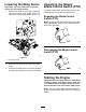
6.Ifyoudesireadditionalheight-of-cutrange,
adjustthefrontandreargaugewheelsonthe
wingdeckasfollows:
A.Removethemountinghardwarefromthe
gaugewheel.
B.Adjustthefrontandreargaugewheels
totheappropriateholelocation(seethe
chartbelowandFigure27)andinstallthe
mountinghardware.
HoleLocation
Height-of-CutRange
Tophole(-1onthedecal)25to89mm(1to3-1/2inches)
Middlehole(0onthedecal)51to114mm(2to4-1/2
inches)
Bottomhole(+1onthedecal)76to140mm(3to5-1/2
inches)
g212253
Figure27
Height-of-cutrange
1.Tophole(-1onthedecal)
2.Middlehole(0onthedecal)
3.Bottomhole(+1onthedecal)
C.Repeatfortheotherwingdeck.
AdjustingtheAnti-Scalp
Rollers
Formaximumdeckotation,installtherollers1hole
positionlower.Rollersshouldmaintaina6mm(1/4
inch)clearancetotheground.Donotadjustthe
rollerstosupportthedeck.
1.Parkthemachineonalevelsurface.
2.Disengagetheblade-controlswitch(PTO),move
themotion-controlleverstotheNEUTRAL-LOCK
position,andengagetheparkingbrake.
3.Shutofftheengine,removethekey,andwait
forallmovingpartstostopbeforeleavingthe
operatingposition.
4.Afteradjustingtheheightofcut,adjustthe
anti-scalprollersbyremovingthemounting
hardware.
5.Placetherollersin1ofthepositionsshownin
Figure28.
Therollerswillmaintain19mm(3/4inch)
clearancetothegroundtominimizegouging
androllerwearordamage.
g243016
Figure28
Forcuttingheightsabove90mm(3-1/5inches),usethe
bottomhole.Therollersarestilleffectiveagainstscalping.
1.Anti-scalprollermounting
bracket
2.Cuttingheight
6.Torquethenylocnut(3/8inch)to41to47N∙m
(30to35ft-lb)asshowninFigure29.
30