
Service Manual
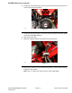


Table Of Contents
- Revision History
- Preface
- Chapter 1 : Safety
- Chapter 2 : Specifications and Maintenance
- Chapter 3 : Troubleshooting
- Chapter 4 : Engine
- Chapter 5 : Chassis
- General Information
- Service and Repairs
- Right Console Replacement
- Left Console Replacement
- Throttle Cable Assembly Replacement
- Choke Cable Assembly Replacement
- Seat Replacement
- MYRIDE® Replacement
- Fuel Tank Replacement
- Park Brake Handle Assembly Replacement
- ROPS (Roll Over Protection System) Replacement
- Caster Fork and Bearing Replacement
- Caster Wheel Rebuild
- Motion Control Assembly Replacement
- Chapter 6 : Deck
- Chapter 7 : Drive System
- Chapter 8 : Electrical
- Appendix A: Foldout Drawings
- Electrical Schematic
- Electrical PTO Engaged Schematic
- Electrical Run Position
- Electrical Start Position

MYRIDE®Removal(continued)
g348084
Figure42
11.Removethe½inchcarriageboltfromtheshockmountwhilesupportingthe
frontMYRIDEsubframe.Reinstallthe½inchcarriageboltwiththeMYRIDE
subframerestingagainsttheshockandtighten.
g346226
Figure43
12.LowertheROPStothefull-downposition.
13.Fullyremovethe2(3/8inch)locksnutssecuringthelowerfrontrearshocks
totheROPS(previouslyloosened).
14.Usinganappropriateliftingdevice,slightlyraisetheMYRIDEassemblyand
slidetherearshocksoffthemountstuds,movetotheside.
15.FullyraisetheMYRIDEassemblyoutofthemachine.
MYRIDE®Installation
1.Usinganappropriateliftingdevice,InstalltheMYRIDEassemblyintothe
machine.
2.RaisetheROPS.
3.Installandtightenthe½inchcarriagebolttotheshockmountwhile
supportingthefrontMYRIDEsubframe.
Note:Donotover-tightenthecarriagebolt.Theshockmustpivotfreely.
Chassis:ServiceandRepairs
Page5–22
4000SeriesZMASTER®ServiceManual
3442-427RevA