
Operator's Manual


g298850
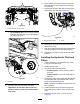
Figure95
1.Topspindlenut3.Bladebolt
2.Flatofthespindleshaft
3.Applycopper-basedlubricantorgreasetothe
threadsofthebladeboltasneededtoprevent
seizing.Installthebladeboltnger-tight.
4.Placeawrenchontheatofthespindleshaft
andtorquethebladeboltto75to81N∙m(55
to60ft-lb).
AdjustingtheSide-to-Side
LevelingandtheBlade
Slope
Checktoensurethatthemowerdeckislevelanytime
youinstallthemowerorwhenyouseeanunevencut
onyourlawn.
Checkthemowerdeckforbentbladespriorto
leveling,andremoveandreplaceanybentblades;
refertoServicingtheCuttingBlades(page64)before
continuing.
Levelthemowerdeckside-to-siderst;thenyoucan
adjustthefront-to-rearslope.
Requirements:
•Themachinemustbeonalevelsurface.
•Alltiresmustbeproperlyinated;refertoChecking
theTirePressure(page55).
1.Parkthemachineonalevelsurface,disengage
theblade-controlswitch(PTO),andengagethe
parkingbrake.
2.Shutofftheengine,removethekey,andwait
forallmovingpartstostopbeforeleavingthe
operatingposition.
3.Checkthetirepressureinthedrivetires;referto
CheckingtheTirePressure(page55).
4.Positionthemowerdeckinthetransport-lock
position.
5.Carefullyrotatethebladesfromsidetoside.
6.Measurebetweenthebladetipandtheat
surface(Figure96).Ifbothmeasurementsare
notwithin5mm(3/16inch),adjusttheleveling;
continuewiththisprocedure.
g037879
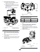
Figure96
1.Bladessidetoside
3.Measurefromthetipofthe
bladetotheatsurface
here.
2.Bladetip
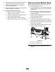
7.Checkthefront-to-rearbladelevel(Figure97).
Ensurethefrontbladetipislowerthantherear
bladetipasshownintheblockheightandrake
table.Ifadjustmentisneeded,continuewiththis
procedure.
g037880
Figure97
1.Bladesfronttorear3.Measurefromthetipofthe
bladetotheatsurface
here.
2.Bladetip
8.Settheanti-scalprollerstotopholesorremove
themcompletelyforthisadjustment.
67