
Service Manual


18 ZT-4400
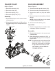
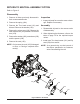
Figure 10, Control Arm
CONTROL ARM ASSEMBLY
RefertoFigure10
Disassembly
1. Remove all items previously discussed in
their recommended order.
2. Remove the lock nut (172) and washer
(160).Discardbothitems.
3. Remove the Torx head screw (156) and
discard.
4. Remove the control arm (154) and spacer
(170).
5. Remove the stud (171) only if damaged.
6. Removetheseal(150).
NOTE: Onlyremovetheseal(150)ifdamaged
orworn,orifdoingacompletedisas-
sembly.
Inspection
1. Inspect all parts for excessive wear or dam-
age. Replace if necessary.
Assembly
1. Reassemble all parts in the reverse order
of disassembly.
2. When tightening the fasteners, refer to the
table on page 15 for the required torque
values.
3. InstallnewTorxheadscrew(156)andlip
seal (150) from seal kit.
NOTE: Asageneralrule,usethelowendof
thetorque specicationon fasteners
whenreassemblingtheunit.
171
170
154
160
172
150
156