
Service Manual


Valves
.
ENGINE TOP END 4-11
Clearance Inspection
NOTE
0 Valve clearance must be checked when the engine is cold (at room
temperature).
ORemove the rocker chamber cover (see Cylinder Head Removal).
l
Place the piston at top dead center (TDC) of the compression stroke
turning the crankshaft clockwise facing the flywheel.
No. 1 Cylinder:
OAlign (!,) mark on the flywheel (1) with (A) mark on the breather
chamber cover (2) as shown.
0 Check the intake and exhaust valves are closed completely, if not turn
the flywheel one turn (360”) clockwise and align both marks on the
flywheel and cover again.
No. 2 Cylinder:
OAlign ($ ) mark on the flywheel with (A) mark on the breather
chamber cover. Follow No. 1 Cylinder alignment procedure described
above.
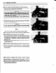
aThen check the clearance.
0 Using a thickness gauge (A), measure the valve clearance between the
rocker arm and the valve stem end.
*If the valve clearance is incorrect, adjust it.
Valve Clearance (when cold)
Intake, Exhaust: 0.25 mm (0.01 in)
:
Clearance AQustrnent
l
Since the valve repairs change the valve clearance, adjust the valve
clearance to the specification.
l
Assemble the cylinder head and install the cylinder head assembly on
the block (see cylinder Head Installation Notes).
l
Turn the crankshaft proper direction until the piston is at TDC of the
compression stroke (described above).
l
Loosen the locknut (C) and valve clearance adjusting screws( 6).
l
insert a 0.25 mm (0.01 in) thickness gauge (A) between the adjusting
screw and valve stem, and tighten the adjusting screw until the
thickness gauge begin to bind between the rocker arm and valve stem
end. Use a sweeping motion with the thickness gauge while making
this adjustment.
l
Holding the adjusting screw with a spanner, tighten the locknut to the
specified torque (see Exploded View).
0 Do not overtighten.