
Service Manual


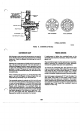


CRANKSHAFT
GEAR PULLER
E MARKS
WHEN
ING TIMING
EARS
FIGURE
11.
TIMING GEAR REMOVAL AND INSTALLATION
PISTONS
AND
CONNECTING
RODS
Observe
the
following procedure when removing pistons
and connecting
rods
from the engine.
1.
Drain oil.
2.
Remove the cylinder head and oil base pan from the
engine.
3.
Remove the ridge from the top of each cylinder with
a ridge reamer before attempting piston removal
(Figure
12).
Forcing the piston from the
cylinder before reaming may
cause
damage
to
the
piston lands and
break
rings.
FIGURE
12.
REMOVING RIDGE
FROM
CYLINDER
4.
Turn the crankshaft until the piston is at the bottom
of
its
stroke and remove the connecting
rod
nuts.
Lift
the
rod
bearing cap from the
rod
and push the
rod
and piston assembly out through the top
of
the
cylinder using a hammer handle.
Do
not scratch the
crankpin and cylinder wall when removing the
piston and
rod.
5.
Mark each piston and
rod
assembly
so
they can
be
returned to their respective cylinders after overhaul.
Keep connecting rod bearing caps with their
respective
rods.
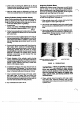
6.
Remove the piston rings from the piston with a
piston ring spreader (Figure 13). Remove the piston
pin retainer and push the piston pin out
FIGURE
13.
REMOVING
PISTON
RINGS
7.
Remove dirt and deposits from the piston surfaces
with an approved cleaning solvent Clean the piston
ring grooves with a groove cleaner
or
the end of a
piston ring filed to a sharp point (Figure
14).
Care
must be taken not to remove metal from the groove
sides.
pistions.
There
materials will
cause
piston
damage.
8.
Clean the connecting rods in solvent. Blow out all
passages with compressed air.
P224
Engines that have been filled with
0.005
inch
(0.1
3
mm)
oversize pistons at the factory are identified by the letter
E
after the serial number. Number is stamped on the
cylinder block and on the unit nameplate.
10-8