
Service Manual


FLYWHEEL
GEAR
COVER
Removing the flywheel is a relatively simple process, but
the following procedure must
be
followed to avoid
damage to the gear case and possible injury to the
operator.
1.
Turn the flywheel mounting screw outward about
two turns.
DO
not remove the screw com-
pletely
since
it
acts as a restrainer
when
the
flysheel
snaps
loose.
If
the
flywheel
is
not
held
by
the
screw,
the
spring
action
in
the
wheel
will
cause
n
to
fly
off
with
great
force
which
can
cause
injury
to
the
operator.
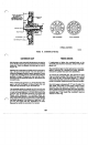
2.
Install
a
puller
bar
on
the
flywheel
(Figure
8).
MOUNTING
SCREW
FIGURE
BLOWER
WHEEL
PULLEY
3.
Turn the puller
bar
bolts
in, alternately, until the
wheel snaps
loose
on the shaft.
similar tool
or
pry
behind
the
DO
not use
a
screwdriver
or
flywheel
against
the
gear
case. The
gear
case
cover
is
die-cast material and
will
break
if
undue
pressure
is
applied
in
this
manner.
4.
Unscrew the puller from the flywheel, remove the
flywheel mounting screw and washer and pull the
flywheel
off
the shaft. Take care not to drop the
wheel.
A
bent
or
broken
fin
will destroy
the
balance.
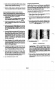
After removing the mounting screws, tap the gear cover
gently with a
soft
faced hammer to loosen
it.
When installing the gear cover, make sure the pin in the
gear cover engages the nylon lined (smooth) hole in the
governor cup. Turn the governor cup
so
the nylon lined
hole is at the three o’clock position.
Use
a small amount
of
grease
to assist in holding governor cup in position.
The smooth side of the governor yoke must ride against
the governor cup. Turn the governor arm and shaft
clockwise
as
far as possible and hold in this position
until the gear cover is installed flush against the
crankcase.
Be
careful not to damage the gear cover oil
seal
(Figure
9).
CUP
SO
PIN
FITS
ROTATE
GOVERNOR
INTO
THE
METAL
BUSHING
IN
THE
CUP
I
GOVERNOR
CUP
GOVERNOR
IF
FEELER
BALL
HAS
ENTER
HOLE
FIGURE
9.
GEAR
COVER
ASSEMBLY