
Service Manual


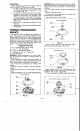


CAM RING REMOVAL
-Control Shall
Insert
cam
Ring
Buttons
Control
Shall
FIG.
55
Inspect rotor bores, bushing and pintle for damage
or excessive clearance. Ball piston to rotor bore clear-
ance
is
select
fit to
.0002-.0006".
When damage
is
found, replace complete rotor assembly.
If
damage
is
not found, reinstall balls in their removed bores and
retain with rubber band.
Slide
cam ring from pivot pin and control shaft in
cover. Then lift ring from cover. Remove control shaft
insert from cam ring.
Remove two buttons from cover.
CAM RING INSPECTION
Cam
Pump
Race
I I
FIG.
56
Inspect area where ball pistons contact race.
This
area must be smooth and completely free of damage.
CHARGE PUMP HOUSING REMOVAL
Pump
Remove bearing retaining ring. Remove shaft re-
Use
1/4”
Allen wrench to remove five
bolts.
taining ring.
IMPORTANT:
Do
not pound on bearing puller while
removing charge pump body. Apply steady pull only.
Do not damage bore or input shaft during removal.
Use two jaw bearing puller, inserted in two notches
machined in housing, to remove charge pump hous-
Ing.
CHARGE PUMP HOUSING DlSASSEMBLY/INSPECTION
Input
Bearing
Square
cut Seal
FIG.
59
FIG.
57
IMPORTANT: Support bottom of input shaft with
2
x
2
x
2 1/2”
wood block with cover assembly placed on flat
surface with input shaft up.
-24-
Remove square seal from housing assembly.
Use
a
bearing puller to remove bearing and seal. Discard
oil
seal.
Inspect ball bearing.
If
damage
is
found, obtain
new bearing.
CHARGE
PUMP
CARRIER
a
PLATE REMOVAL/INSPECTION
Snap
Carrier
Shall
FIG.
60