
Operator's Manual
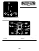


3.Lowertherollbartothedownposition(Figure
8).
g228804
Figure8
1.Rollbarintheupright
position
4.RotatetheROPSknob90
degrees.
2.ROPSknobinthelatched
position
5.ROPSknobinthe
unlatchedposition
3.PulltheROPSknobout.6.Rollbarinthefolded
position
RaisingtheRollBar
Important:Alwaysusetheseatbeltwiththeroll
barintheraisedposition.
1.Raisetherollbartotheoperatingpositionand
rotatetheknobsuntiltheymovepartiallyinto
thegrooves(Figure8).
2.Raisetherollbartothefulluprightpositionwhile
pushingontheupperrollbarsothatthepins
snapintopositionwhentheholesalignwiththe
pins(Figure8).
3.Pushontherollbarandensurethatbothpins
areengaged.
UsingtheSafety-Interlock
System
WARNING
Ifthesafety-interlockswitchesare
disconnectedordamaged,themachinecould
operateunexpectedly,causingpersonal
injury.
•Donottamperwiththeinterlockswitches.
•Checktheoperationoftheinterlock
switchesdailyandreplaceanydamaged
switchesbeforeoperatingthemachine.
Understandingthe
Safety-InterlockSystem
Thesafety-interlocksystemisdesignedtopreventthe
enginefromstartingunlessthefollowingoccurs:
•Theparkingbrakeisengaged.
•Theblade-controlswitch(PTO)isdisengaged.
•Themotion-controlleversareintheNEUTRAL-LOCK
position.
Thesafety-interlocksystemalsoisdesignedtoshut
offtheenginewhenthemotion-controlleversare
movedfromtheNEUTRAL-LOCKpositionwiththe
parkingbrakeengagedorifyourisefromtheseat
whenthePTOisengaged.
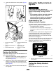
Thehourmeterhasindicatorstonotifytheuserwhen
theinterlockcomponentisinthecorrectposition.
Whenthecomponentisinthecorrectposition,an
indicatordisplaysonthescreen.
g009181
Figure9
1.Indicatorsdisplaywhentheinterlockcomponentsareinthe
correctposition
TestingtheSafety-Interlock
System
ServiceInterval:Beforeeachuseordaily
19