
Service Manual


HYDRAULIC SYSTEM
5-13Toro Z Master G3 3000/5000/6000 Series Service Manual
5
21. Repeat steps 17 thru 20 to install the brake caliper
on the opposite wheel hub.
Note: If a brake component or wheel hub is being
replaced, follow the “Burnishing the Brake”
procedure on page 5-20.
19. Repeat step 18 to install the other brake mounting
bolt.
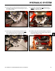
20. Tighten the brake cable swivel nut to secure (Fig.
309).
Adjust the Parking Brake:
Note: For this example, the left side brake is being
adjusted; the right side brake adjustment is
the same procedure.
22. Open the valve(s) (vertical position) on the UHTs
(Fig. 310).
Fig. 309 PICT-8668a
Fig. 310 PICT-8677a
23. Ensure the parking brake is disengaged.
24. Using your thumb, push the caliper lever arm for-
ward to engage the brake pads on the wheel hub
until the lever stops (Fig. 311).
Note the order of the standard nut and the lock nut
on the end of the brake cable.
Fig. 311 PICT-8679a
A. Standard nut B. Lock nut
A
B