
Operator's Manual


g298850
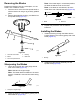
Figure98
1.Topspindlenut3.Bladebolt
2.Flatofthespindleshaft
3.Applycopper-basedlubricantorgreasetothe
threadsofthebladeboltasneededtoprevent
seizing.Installthebladeboltnger-tight.
4.Placeawrenchontheatofthespindleshaft
andtorquethebladeboltto75to81N∙m(55
to60ft-lb).
LevelingtheMowerDeck
1.Parkthemachineonalevelsurface,disengage
theblade-controlswitch(PTO),andengagethe
parkingbrake.
2.Shutofftheengine,removethekey,andwait
forallmovingpartstostopbeforeleavingthe
operatingposition.
3.Checkthetirepressureinthedrivetires;referto
CheckingtheTirePressure(page50).
4.Positionthetransportlockinthelatching
position.
5.Pushthedeck-liftpedalallthewayforwardand
thedecklatchesatthe14cm(5-1/2inches)
transportposition(Figure99).
g027343
Figure99
1.Deck-liftpedal
3.Transportlock
2.Height-of-cutpin
6.Inserttheheight-adjustmentpinintothe7.6cm
(3inches)cutting-heightlocation.
7.Releasethetransportlockandallowthedeckto
lowertothecuttingheight.
8.Raisethedischargechute.
9.Onbothsidesofthedeck,measurefromthe
levelsurfacetothefronttipoftheblade(Postion
A)asshowninFigure100.
Note:Themeasurementshouldread7.6mm
(3inches)
66