
Operator's Manual


14.Torquethe2boltsto37to45N∙m(27to33ft-lb).
15.Onbothsidesofthedeck,measurefromthe
levelsurfacetothebacktipoftheblade(postion
B)asshowninFigure113.
Note:Themeasurementshouldread8.3cm
(3-1/4inches)
16.Finetunethescrewadjusterbyturningittoget
8.3mm(3-1/4inches)height(Figure114).
Toincreasetheheight,turntheadjustmentnut
clockwise;todecrease,turncounterclockwise.
17.Measureuntilall4sidesarethecorrectheight.
18.Tightenallofthenutsonthedeck-lift-arm
assemblies.
19.Lowerthedischargechute.
RemovingtheMowerDeck
Lockoutthespring-loadeddeckarmsbeforeservicing
orremovingthemowerdeck.
WARNING
Deck-liftarmassemblieshavestoredenergy.
Removingthedeckwithoutreleasingthe
storedenergycancauseseriousinjuryor
death.
Donotattempttodisassemblethedeckfrom
thefrontframewithoutlockingoutthestored
energy.
1.Parkthemachineonalevelsurface,disengage
theblade-controlswitch(PTO),andengagethe
parkingbrake.
2.Shutofftheengine,removethekey,andwait
forallmovingpartstostopbeforeleavingthe
operatingposition.
3.Placetheheightadjustmentpininthe7.6cm(3
inch)cutting-heightlocation.
Note:Thislocksthedeck-liftarmsinthelowest
positionwhenthedeckisremovedandthe
storedenergyinthedeckspringisreleased.
4.Removethebeltcovers.
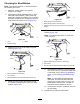
5.Liftuptheoorpanandinsertaratchetintothe
squareholeinthedeckidler(Figure117).
6.Rotatethedeckidlerclockwiseandremovethe
mowerbelt(Figure117).
g009038
Figure117
1.Clutchpulley5.Squareholeintheidler
armfortheratchet
2.Mowerbelt
6.Idlergreasetting
3.Spring-loadedidlerpulley
7.Beltguide
4.Ratchet
7.Removeandretainthehardwareonbothsides
ofthedeckasshowninFigure118.
g010252
Figure118
1.Rightstabilizer
2.Deckstrut(rightsideshown)
3.Removetheshoulderboltandnut.
4.Removetheshoulderboltandnut.
76