
Service Manual


260 Series Tractor Service Manual 5 - 3
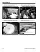
GEAR DRIVE
9. Place a floor jack under the transaxle. Remove
the bolts holding the front right and left torque
straps (Figure 177).
Figure 177
MVC-250X
10. Remove the four carriage bolts, washers, and nuts
securing each side of the transaxle axle housing
to the frame (Figure 178).
Figure 178
MVC-252X
11. Lower the transaxle out of the frame (Figure 179).
Figure 179
MVC-253X
Installation – Gear Drive Transaxle
1. Raise the transaxle up toward the frame and
install the four carriage bolts, washers, and nuts.
On the right side, make sure the brake stop
bracket is installed between the transaxle and the
frame (Figure 180).
Figure 180
MVC-256X