
Service Manual


HYDRO-GEAR TRANSAXLE
4 - 6 260 Series Tractor Service Manual
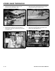
7. Reconnect the cruise control magnet and the
reverse plunger switch if applicable (Figure 136).
Figure 136
MVC-137X
8. Install the brake arm with the brake rod and brake
spring, on the brake stud. Install the castle nut,
but do not install the cotter pin until brake
adjustment has been performed (Figure 137).
Refer to ”Brake Adjustment – Hydro-Gear
Transaxle" on page 4 - 9.
Figure 137
MVC-135X
9. Connect the free wheeling valve rod and the vent
hose clamp (Figure 138).
Figure 138
MVC-133X
10. Reconnect the gas line to the gas tank and install
the gas tank (Figure 139).
Figure 139
MVC-160X