
Service Manual


22
310-3000 IHT
1
52
53
54
29
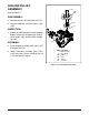
REF. Part Name
1 Main Housing
29 Screw
52 Gerotor Assembly
53 O-ring
54 Gerotor Cover
52
53
54
CHARGE PUMP ASSEMBLY
Refer to Figure 13.
DISASSEMBLY
Note: Before disassembling, note the ori-
entation of the charge pump cover (54).
Scribe or mark the charge pump cover
(54) for correct orientation during assem-
bly.
1. Remove two screws (29) from the charge
pump cover (54), and remove charge pump
cover (54).
2. Remove o-ring (53) and gerotor assembly
(52).
INSPECTION
1. Inspect gerotor assembly (52), cavity of
charge pump cover (54), plate on which cover
is mounted for damage or excessive wear.
ASSEMBLY
1. Install gerotor assembly (52) onto input shaft
(12) (not shown).
2. Install new O-ring (53) into charge pump cover
(54).
3. Install charge pump cover (54), making sure
it is properly oriented.
4. Secure charge pump cover (54) by installing
two screws (29), per Table 5, Page 13.
Figure 13. Charge Pump Assembly