
Operator's Manual


ControlsSystem
Maintenance
Adjustingthe
Control-HandlePosition
Thereare2heightpositionsforthecontrol
levers—highandlow.Removetheboltstoadjustthe
heightfortheoperator.
1.Parkthemachineonalevelsurface,disengage
theblade-controlswitch(PTO),andengagethe
parkingbrake.
2.Shutofftheengine,removethekey,andwait
forallmovingpartstostopbeforeleavingthe
operatingposition.
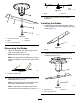
3.Loosentheboltsandangenutsinstalledinthe
levers(Figure57).
4.Aligntheleversinthefront-to-rearpositionby
bringingtheleverstogethertotheNEUTRAL
position,andslidethemuntiltheyarealigned,
thentightenthebolts(Figure58).
g009040
Figure57
1.Bolt
3.Controllever
2.Handle4.Nut
g009195
Figure58
5.Iftheendsofthelevershitagainsteachother,
refertoAdjustingtheMotion-ControlLinkage
(page51).
6.Repeattoadjustthecontrollevers.
Adjustingthe
Motion-ControlLinkage
Locatedoneithersideofthemachine,belowtheseat,
arethepump-controllinkages.Rotatingtheendnut
witha1/2-inchdeepsocketwrenchallowsnetuning
adjustmentssothatthemachinedoesnotmovein
neutral.Anyadjustmentsshouldbemadeforneutral
positioningonly.
WARNING
Toadjustthemotioncontrol,youmustrun
theengineandturnthedrivewheels.Contact
withmovingpartsorhotsurfacesmaycause
personalinjury.
Keepyourngers,hands,andclothingclear
ofrotatingcomponentsandhotsurfaces.
1.Parkthemachineonalevelsurface,disengage
theblade-controlswitch(PTO),andengagethe
parkingbrake.
2.Shutofftheengine,removethekey,andwait
forallmovingpartstostopbeforeleavingthe
operatingposition.
3.Pushthedeck-liftpedal,removetheheight-of-cut
pin,andlowerthemowerdecktotheground
51