
Service Manual


MOWER
6 - 8 XL Lawn Tractor Service Manual
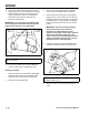
4. Remove the height-of-cut lift assist spring from
the retaining bolt (Figure 212), using the
spring tool
provided with the machine. The spring
is between the frame and the right rear wheel.
Figure 212
1851
5. Move the height-of-cut lever (deck lift) into the “A”
notch.
6. Unhook the blade control (PTO) cable ring end
from the idler spring (Figure 213).
7. Remove rubber wiper and jam nut from blade
control (PTO) cable at mounting bracket. Slide the
cable from the bracket (Figure 213).
8. Move the cable out of the way and lay inside
frame rail so it cannot get caught in drive belts or
pulleys.
Figure 213
m-2384
(A) Spring
(B) Bolt
(C) Spring Tool
CAUTION
POTENTIAL HAZARD
• The height-of-cut lever (deck lift) is spring-
tensioned.
WHAT CAN HAPPEN
• When the mower is being removed, this
spring-loaded mechanism could suddenly
release and injure you or someone else.
HOW TO AVOID THE HAZARD
• Move the height-of-cut lever (deck lift) to the
“D” position and remove the height-of-cut lift
assist spring to release the spring tension.
(A) Blade Control (PTO) Cable
(B) Ring End
(C) Idler Spring
(D) Jam Nut
(E) Mounting Bracket
(F) Rubber Wiper