
Service Manual


MOWER
A6-2 XL Lawn Tractor Service Manual
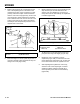
4. If adjustment is needed, turn the adjustment nut
located on each end of the brake rods to achieve
.06” – .12” (1.5mm – 3.0mm) gap.
Fig A6 003 94-2888-5
1. Lower the mower to the lowest height of cut position.
2. With the engine OFF, engage the mower (PTO)
lever.
3. Check the clearance between the brake pads on the
brake arm assemblies on the right and left mower
drive pulleys. They should be set between .06”
– .12” (1.5mm – 3.0mm) away from the deck pulleys
(Fig. A6 003).
44” Mower Brake Adjustment
44” Mower with Manual PTO Clutch
Fig A6 004 fi g. 35 m-1851
1. Park the tractor on a level surface.
2. Disengage the PTO and set the parking brake.
3. Stop the engine, remove the key, and wait for all
moving parts to stop before leaving the operating
position.
4. Move the height-of-cut lever into the D notch.
5. Remove the height-of-cut lift assist spring from the
retaining bolt. The spring is between the frame and
the right rear wheel (Fig. A6 004).
Note: Use the spring tool provided with the
machine.
Removing 38” Mower with Electric PTO
Clutch
38” Mower with Electric PTO Clutch
A
When you remove the mower, the spring-tensioned
height-of-cut lever could suddenly release and injure
you or someone else.
Move the height-of-cut lever to the “D” position and
remove the height-of-cut assist spring to release the
spring tension.
CAUTION
!!
A. Spring C. Spring tool
B. Bolt
A
B
C
AA
D
B
B
C
A. Mower pulleys C. Brake rods
B. Adjustment nuts D. Brake pad gap .06”
– .12” (1.5 – 3.0mm)